Table of Contents
Advertisement
Quick Links
Advertisement
Table of Contents

Subscribe to Our Youtube Channel
Related Manuals for Neol ePowerswitch 1G R2


Summary of Contents for Neol ePowerswitch 1G R2
-
Page 1: User Guide
User Guide ePowerSwitch 1G Version 2.2.0.6 www.neol.com... - Page 2 Trademarks Neol and ePowerSwitch are registered trademarks of NEOL S.A.S. All other brand names and product names used in this book are trade names, service marks, trademarks, or registered trademarks of their respective owners.
-
Page 3: Table Of Contents
CONTENTS SAFETY INSTRUCTIONS: To be read before use! ..................4 1. DESCRIPTION ............................5 1.1 Diagram ............................... 5 1.2 Package list ............................6 2. INSTALLATION ............................7 3. CONFIGURATION ............................ 8 3.1. Configuration through the LAN using the Finder program ..............8 ... -
Page 4: Safety Instructions: To Be Read Before Use
This equipment is designed to be installed on a dedicated circuit that must have a circuit breaker or fuse protection. • The electrical power sockets used to plug the power cords of the ePowerSwitch devices must be close to the ePowerSwitch devices and easily accessible. •... -
Page 5: Description
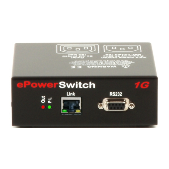
(KVM Switch, console server...) and to trigger a soft shutdown of a server with shutdown capabilities. The ePowerSwitch 1G supports the HTTP, DHCP, Syslog, SNMP and SNTP protocols. 1.1 Diagram The front panel of the ePowerSwitch 1G RJ45 Connector LEDs... -
Page 6: Package List
RS232 (SUB-D 9F Connector) Serial port RS232 with DB-9 female connector Pinout 2 = TxD 3 = RxD 5 = Gnd The back of the ePowerSwitch 1G Power input Power outlet Power outlet 230 VAC – 10 Amp 230 VAC max 10 Amp 1.2 Package list... -
Page 7: Installation
Make sure that the ePowerSwitch 1G is powered off. Connection instructions 1. Use a shielded RJ45 network cable to connect your ePowerSwitch 1G to the network. 2. Use an appropriated three-wire power cord (two poles plus ground) to connect your electrical device to the ePowerSwitch 1G unit. -
Page 8: Configuration
Ask your network administrator for the parameters to use. There are three methods to configure the network parameters of the ePowerSwitch 1G 3.1. Configuration through the LAN using the Finder program It is the simplest and fastest configuration method if you use Windows as operating system. - Page 9 Firmware version of the ePowerSwitch 1G Finder authorized: The Network parameters of the ePowerSwitch 1G can be configured through a Local Area Network using the provided Finder Program. It is a simple and fast configuration method if you use Windows as operating system.
-
Page 10: Configuration Through An Rs232 Terminal Connection
8 bits Stop bit: Flow control: The serial cable provided with the ePowerSwitch-is a standard straight extension cable with DB9 connectors. This cable is intended to connect the serial port of the ePowerSwitch to a serial port of a PC. -
Page 11: Restore To Default Factory Settings
3.2.2. Restore to default factory settings If you want to restore the ePowerSwitch to factory settings, you can reset it to default value using following procedure: 1. Use the supplied RS232 cable to connect the ePowerSwitch-to an available serial port of your PC. -
Page 12: Configuration Through The Lan Using A Standard Browser
Gateway: 255.255.255.0 1. Open your Web browser and type following IP address: http://192.168.100.200/sysadmin.htm 2. Enter the administrator name and password (default for both = admin) 3. The home page appears, allowing you to configure all settings of your ePowerSwitch 1G... -
Page 13: General / Ip Configuration
3.3.1. General / IP configuration This page enables you to define all the IP parameters of the ePowerSwitch 1G DHCP Client enabled: Check this box is you want to obtain the IP address, the subnet mask and the default gateway for your ePowerSwitch 1G via DHCP. -
Page 14: General / System Time
NTP timeservers. Current System Time: This field shows the current system time of the ePowerSwitch 1G As the system time is displayed through the browser, a small difference (1 to 2 sec) can appear as compared to the exact hour. -
Page 15: General / Snmp
MIB file enables to remotely read out the status of all power outlets and the values of all sensors (temperature, humidity, ambient light). It also enables to control individually all power outlets and all groups of power outlets. The MIB file is stored on the ePowerSwitch 1G and can be downloaded from the General / Tools Page. -
Page 16: General / Tools
Click this button to save the current system settings onto your local hard drive. Load: Click this button and select a settings file you want to download to the ePowerSwitch 1G Restore: Click this button if you want to restore the factory default settings. -
Page 17: Settings / Accounts
3.3.5. Settings / Accounts 3.3.5.1 Settings / Accounts This page is used to create, activate, deactivate, modify and delete up to 40 accounts. - To activate or deactivate an account, check or uncheck the corresponding checkbox. - To modify an account, click on "Edit" next to the corresponding account. - To delete an existing account, click on "Delete"... - Page 18 The selected Inputs/Outputs are marked dark blue and their IDs are listed at the right side of the Input/Output field. The ePowerSwitch 1G supports number of peripherals which are clearly identified by specific ID Codes.
-
Page 19: Settings / Accounts / Hidden
3.3.5.2 Settings / Accounts / Hidden Page account This account is intended for developers who want to implement the power outlet control in own programs. If activated, they can access to a special page named hidden.htm and control individually the power outlets using simple commands. - Page 20 Device In this drop-down list, choose the device from which one you want to add an Inputs to the current account. - Only properly connected devices or devices which already have been connected to the Power Switch appears in this field. - Each peripheral is clearly identified by its own ID followed by the name given during the configuration.
-
Page 21: Settings / Groups N/A
3.3.6. Settings / Groups N/A 3.3.7. Settings / Peripherals N/A This page enables to label the device, the power outlet of the ePowerSwitch and the shutdown function. Names of up to 32 alphanumeric characters in length are supported and appear in log files, Syslog messages and SNMP traps to avoid confusions. - Page 22 Click on this button to create a new rule. Name: In this field, enter the name you want to give to the power outlet of the ePowerSwitch. The name can be from 1 to 32 characters long and can contain alphanumeric characters.
-
Page 23: Settings / Rules
3.3.8. Settings / Rules Rules are used to control actions according to a specific event. For example, you can define rules to switch the power outlet OFF from Friday evening to Monday morning. - To remove an existing rule, click on "Delete" of the corresponding rule. - To modify a rule, click on "Edit"... - Page 24 This rule is used to control actions according to the response to a Ping command. This rule can be used to check if a computer or any IP device is connected to the network. If the host doesn't reply, the ePowerSwitch can automatically restart the powered device. 4. Scan Monitoring Rule: This rule is used to control actions according to the response to a Scan command.
-
Page 25: Settings / Rules - Schedule Rule
Rule ID: The ePowerSwitch 1G automatically creates an ID Code to clearly identify each rule. All the ID Codes used to identify rules start with the letter "R" followed by a number from 1 to 32. If you delete a rule in the middle of the Rule list, the number of this rule will only be used again if no other rule is available. - Page 26 65535 seconds. - If you choose 0 second, the delay will be the delay defined in the ePowerSwitch power outlet settings. - If you choose a delay different from 0, the delay will replace the delay defined in the ePowerSwitch power outlets settings.
-
Page 27: Settings / Rules - Timer Rule
3.3.8.2. Settings / Rules - Timer Rule This rule used trigger some actions according defined time table. For instance, you could create a rule to switch OFF a Power Outlet every Friday at 6 PM and create another rule to switch the Power Outlets ON again every Monday at 8 AM. Activated This check box must be checked to activate the rule. - Page 28 65535 seconds. - If you choose 0 second, the delay will be the delay defined in the ePowerSwitch power outlets settings. - If you choose a delay different from 0, the delay will replace the delay defined in the ePowerSwitch power outlets settings.
-
Page 29: Settings / Rules - Ping Monitoring Rule
This rule can be used to check if a computer or any IP device is connected to the network. It sends ping packets and listens for replies from the specific host. If the host doesn't reply, the ePowerSwitch 1G automatically switch the powered device off and after a specified delay, switch it again on (for details see Ping &... - Page 30 65535 seconds. - If you choose 0 second, the delay will be the delay defined in the ePowerSwitch power outlets settings. - If you choose a delay different from 0, the delay will replace the delay defined in the ePowerSwitch power outlets settings.
-
Page 31: Settings / Rules - Scan Monitoring Rule
3.3.8.4. Settings / Rules - Scan Monitoring Rule This rule can be used to check if a specific protocol is available on a server (for example HTTP, FTP, Telnet, POP...). If the connection is possible, ePowerSwitch 1G knows that a server program is running there. - Page 32 65535 seconds. - If you choose 0 second, the delay will be the delay defined in the ePowerSwitch power outlets settings. - If you choose a delay different from 0, the delay will replace the delay defined in the ePowerSwitch power outlets settings.
-
Page 33: Settings / Shutdowns
3.3.9. Settings / Shutdowns This power switch supports shutdown facilities of 1 server via its Serial RS232 interface. - To remove an existing Shutdown association, click on "Delete" of the corresponding rule. - To modify a Shutdown rule, click on "Edit" of the corresponding rule. This page is used to create, modify and delete a Shutdown Association. - Page 34 Shutdown Outputs In this field, choose the output which will be used to trigger the Shutdown. - To select an output, select the output you want to add in the left field and click on the Arrow button, the output will then appear in the right field. - To remove the selected output, select this output in the right field and click on the Arrow button, the output will then appear in the left field.
-
Page 35: Misc / Control Panel
3.3.10. Misc / Control Panel This page is very helpful for the administrator because it gives a complete overview. At a glance, the administrator can check the status of the power outlet. -
Page 36: Misc / Rule Panel
The page is automatically refreshed every 10 seconds. Unlike a standard session, the web server of the ePowerSwitch 1G won’t automatically close this kind of session. Opening many sessions of this affects the performances of the web server. -
Page 37: Misc / Log
3.3.12. Misc / Log The log file keeps a running log of events and activities occurring on the device. The logs are automatically cleared when the device is rebooted. The file will display 10 recent logs. -
Page 38: Misc / Log Settings
3.3.13. Misc / Log Settings This page allows you to configure the logs. The Log file is used by the system to record actions, warnings, errors and problems. It is often quite useful to discover the causes of tricky problems. The messages recorded in the log file and sent as copy to a Syslog server are classified into 8 severity levels (Emergency, Alert, Critical, Error, Warning, Notice, Informational and Debug). -
Page 39: Power Outlet Control
. The browser displays the authentication dialog box. 2. Enter a user name and its corresponding password. The status of the ePowerSwitch 1G is displayed. 3. In the drop-down list, choose the power control unit you want to control or the rule for which you want to know the status. -
Page 40: Through A Serial Connection
4.2. through a serial connection The power outlet of the ePowerSwitch can be controlled using a simple ASCII protocol over an RS232 serial connection. 1. Use the supplied RS232 serial cable to connect the ePowerSwitch-to an available serial port of your 2. -
Page 41: Through The Network Using Simple Commands In Your Own Program
4.2. through the network using simple commands in your own program Developers who want to implement the power outlet control in own programs can access to a special page named hidden.htm and control individually the power outlets using simple commands. To configure the Hidden Page Account, go to Settings / Accounts. - Page 42 Device In this drop-down list, choose the device from which one you want to add Inputs or Outputs to the current account. - Only properly connected devices or devices which already have been connected to the Power Switch appears in this field. - Each peripheral is clearly identified by its own ID followed by the name given during the configuration.
- Page 43 The first command must be preceded by a "?" Commands can be concatenated using the character "&" Commands can be specified in upper case, lower case or mixed case Example: if you want to switch to OFF the Power Outlet #1, type in: http://192.168.100.201/hidden.htm?M0:O1=OFF r Web browser will no w display:...
-
Page 44: Appendix
(Reboot function). - The Supervision function works only if the ePowerSwitch 1G is connected to the LAN. - The Ping and Scan functions can be used separately or together. -
Page 45: Technical Data
5.2. Technical Data Network standards: IEEE 802.3, 10 / 100 BASE-T Network protocols: TCP/IP, HTTP Network connection: RJ-45 connector for STP CAT5 Max. network cable length 100 meters Serial connection: RS232, SUB-D 9 female Operating temperature: 0°C to +40°C Operating humidity: 10% to 80% RH (not condensing) Dimensions (LxDxH): 185 x 103 x 43 mm... -
Page 46: Syslog Messages: Severity Level Definitions
5.4. Syslog Messages: Severity Level Definitions The Emergency level is the most severe type of message generated by ePowerSwitch 1G and the Debug severity level is the least severe one. Severity Level 0, Emergency: The following messages appear at severity 0:... -
Page 47: Statement Of Conformity
NEOL S.A.S 4 Rue Nationale 67800 BISCHHEIM -FRANCE Type of Equipment: Power distribution and control unit Type Designation: ePowerSwitch 1G Reference: ePowerSwitch 1G Years of Manufacture: 2011 We, the undersigned, hereby declare that the equipment specified above conforms to the above directives.
Need help?
Do you have a question about the ePowerswitch 1G R2 and is the answer not in the manual?
Questions and answers