Table of Contents
Advertisement
Quick Links
Advertisement
Chapters
Table of Contents

Subscribe to Our Youtube Channel
Related Manuals for Neol 8XS R2


Summary of Contents for Neol 8XS R2
- Page 1 User Guide ePowerSwitch 8XS R2 Version 4.0.1.0 www.neol.com...
- Page 2 NEOL S.A.S assumes no responsibility for errors within the documentation, the hardware or the software. NEOL S.A.S reserves the right to change programs or the documentation from time to time without informing the user, errors and omissions excepted.
-
Page 3: Table Of Contents
CONTENTS SAFETY INSTRUCTIONS: To be read before use! ..........3 Consignes de sécurité : à lire avant utilisation ! ........... 4 1. DESCRIPTION ....................5 1.1. Package list ............................5 1.2 Compatibility tables ..........................5 3. Diagram ......................6 3.1. Front panel ............................6 3.2. -
Page 4: Safety Instructions: To Be Read Before Use
SAFETY INSTRUCTIONS: To be read before use! NOTE The ePowerSwitch devices can only be installed by qualified people with the following installation and use instructions. The manufacturer disclaims all responsibility in case of a bad utilization of the ePowerSwitch devices and particularly any use with equipments that may cause personal injury or material damage. -
Page 5: Consignes De Sécurité : À Lire Avant Utilisation
Consignes de sécurité : à lire avant utilisation ! Français Remarque Les équipements ePowerSwitch ne peuvent être installés que par un personnel qualifié. Le fabricant décline toute responsabilité en cas de mauvaise utilisation des équipements ePowerSwitch et tout particulièrement en cas d’utilisation avec des équipements pouvant occasionner des blessures corporelles ou des dommages matériels. -
Page 6: Description
1. DESCRIPTION ePowerSwitch 8XS Satellite is a power distribution and control unit that enables power management of 8 devices through an RS-232 or RS-485 connection. The ePowerSwitch 8XS has two separate power inputs of 10 Amp to increase the security and the load available on the power outlets. -
Page 7: Diagram
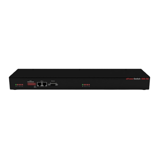
3. Diagram 3.1. Front panel LEDs Dip Switches xBus RS232 LEDs A: Power supply A (Slct) RJ45 connector SUB-D9F Connector B: Power supply B for Output 1-4 1 - 4: Physical address of for conection and for power outlet control for Output 5-8 1-4: Status Outlets 1-4 the ePowerSwitch... -
Page 8: Back
3.2. Back Power outlets (Group A) Power outlets (Group B) Power outlets 1 – 4 Power outlets 5 – 8 230 VAC max 10 Amp 230 VAC max 10 Amp Power input B Power input A 230 VAC – 10 Amp 230 VAC –... -
Page 9: Connection To A Master
4. Connection to an ePowerSwitch Master unit Make sure all the ePowerSwitch devices are powered off. 1. Use the supplied RJ45 Network Cable or any other RJ45 Network Cable to connect an ePowerSwitch 8XS to the xBus interface of: - an ePowerSwitch 4M+ - an ePowerSwitch 8M+ - an ePowerSwitch 8M+/32 - an ePowerSwitch 8XM or 8XM+... -
Page 10: Controlling The Satellite Power Outlets Through The Master Web Server
5. Controlling the Satellite power outlets through the Master Web Server Start your Web browser and type the IP address of your ePowerSwitch Master or your VizioGuard RMS system. The browser displays the authentication dialog box. Enter a user name and its corresponding password. If you log in as system administrator, you will be able to: - control individually all the power outlets and all the power outlets groups of the Master, - control all the power outlets and all the power outlet groups of the connected satellites,... -
Page 11: Controlling The Satellite Power Outlets Using A Terminal Connection
6. Controlling the Satellite power outlets using a Terminal Connection The power outlets of the ePowerSwitch 8XS can be individually controlled and the status of each power outlet can be read out using a simple ASCII protocol through a serial connection. The connection can be done either using the RS232 or the RS485 port of the ePowerSwitch 8XS. -
Page 12: Controlling Of The Power Outlet(S)
6.3.1. Controlling of the power outlet(s) This command enables to control individually each power outlet or all power outlets of the same ePowerSwitch 8XS in one command. Command to be sent to the ePowerSwitch 8XS: Pxy=z[CR] Pxy=z,t [CR] Pxy=z,t [CR] Reply from the ePowerSwitch 8XS: Pxy=z[CR] Pxy=z,t... -
Page 13: Reading Out The Power Outlet Status
6.3.2. Reading out the power outlet status This command enables to read out the status of each power outlet. Command to be sent to the ePowerSwitch 8XS: Rxy[CR] Reply from the ePowerSwitch 8XS: Rxy=z[CR] Explanations: Parameter Value Function/Remark address of the ePowerSwitch 1 to 16 specifies the address of the ePowerSwitch 8XS number of the Power Outlet... -
Page 14: Setting Of The Power Up Delays
6.3.3. Setting of the power up delays This command enables to set the Power Up Delay individually for each power outlet. The Delay value can be between 1 and 255 seconds (4 min 15 sec). Command to be sent to the ePowerSwitch 8XS: TUxy=z[CR] Reply from the ePowerSwitch 8XS: TUxy=z[CR]... -
Page 15: Setting The Restart Delays
6.3.5. Setting the restart delays This command enables to set the Restart Delay individually for each Power Outlet. The Delay value can be between 1 and 255 seconds (4 min 15 sec). Command to be sent to the ePowerSwitch 8XS: TRxy=z[CR] Reply from the ePowerSwitch 8XS: TRxy=z[CR]... -
Page 16: Setting The Power Up Default Status
6.3.7. Setting the power up default status This command enables to set the power up default status individually for each power outlet. Settings can be "always On", "Always Off" or "Last memorized Status" before power failure. Command to be sent to the ePowerSwitch 8XS: DPxy=z[CR] Reply from the ePowerSwitch 8XS: DPxy=z[CR]... -
Page 17: Reading Out The Switching Counter Values Of The Relays
6.3.9. Reading out the switching counter values of the relays This command enables to read out the number of power up cycles of the ePowerSwitch 8XS and the number of switching cycles (Off to On) of each power outlet. Command to be sent to the ePowerSwitch 8XS: Cxy[CR] Reply from the ePowerSwitch 8XS: Cxy=z[CR]... -
Page 18: Resetting The Switching Counter Values Of The Relays
6.3.10. Resetting the switching counter values of the relays This command enables to reset the switching counter values of the Relays. Command to be sent to the ePowerSwitch 8XS: /RC[CR] Reply from the ePowerSwitch 8XS: No reply The ePowerSwitch 8XS accepts lower case and upper case commands. The ePowerSwitch 8XS sends its reply only after having received a valid command terminated by the character [CR]. -
Page 19: Technical Data
Technical Data Network connection RJ-45 connector for UTP CAT5 Max. network cable length 100 meters (not included) Serial connection RS232, SUB-D 9 female Connection Bus RS-485, RJ-45 Nominal input voltage 230 V/50Hz Input power outlet IEC-320 Output voltage 230 V/50Hz Output power outlet IEC-320 Maximum total current... -
Page 20: Statement Of Conformity
Statement of Conformity STATEMENT OF CONFORMITY NEOL S.A.S. declares that this equipment is in compliance with the Electromagnetic Compatibility Directive and the Low Voltage Directive: Application of Council Directives: 2004/108/EEC Standards to Which Conformity declared: EN 60950-1, EN 55022, EN 55024 Manufacturer's Name and Address: NEOL S.A.S.
Need help?
Do you have a question about the 8XS R2 and is the answer not in the manual?
Questions and answers