Table of Contents
Advertisement
Advertisement
Table of Contents

Related Manuals for Star Trac Spinning Computer

Summary of Contents for Star Trac Spinning Computer
- Page 1 Spinning Computer ® User Manual Installation, Service and Instructor Education...
-
Page 3: Table Of Contents
Mounting Computer On Handlebars - Spinner ® Mounting Computer On Handlebars - Spinner Sport / Fit / Velo ® Mounting Computer On Handlebars - Pro 7070 / Elite 7080 / NXT 7090 Maintenance Checklist FAQs and Troubleshooting Spinning Instructor Education ®... -
Page 4: Fcc Regulatory Statements
(1) this device may not cause harmful interference, and (2) this device must accept any interference received, including interference that may cause undesired operation. 2. Changes or modifications not expressly approved by Star Trac could void the user’s authority to operate the equipment. -
Page 5: Parts List
M6x30 Computer Clamp Screw for Rhino Horn Before installing the Spinning Computer, verify that all the parts needed for mounting onto bikes are ® included. If any of the items are missing, call Star Trac at 800-503-1221 714-669-1660 to order a... -
Page 6: Marketing Statement Regarding Heart Rate
Computer: ® Star Trac takes the acquisition and accuracy of heart rate very seriously and has developed a system to perform to the best ability that technology will allow. Star Trac has engineered a product that has taken every precaution possible to acquire an accurate heart rate signal as well as eliminate “crosstalk”... - Page 7 4) Calorie calculations are displayed as a summary only. 5) Cell phones, televisions, speakers and other electronic devices can cause interference with the operation if they are in close proximity to the Spinning Computer and/or ® transmitter. If there are any questions regarding operation or usage of...
-
Page 8: Specifications
Specifications Computer: Heart Rate Range: Approximately 25”- 30” (63 cm - 76 cm) from computer to users HR chest strap Qty. 4 AA Alkaline Battery: Battery life expectancy: 1 year (depending on use and backlight usage) Cadence Sensor: Battery: Lithium CR2032 Approximately 1 year in a commercial environment (depending on use) Battery life expectancy: Distance to magnet:... -
Page 9: How It Works
• The heart rate (HR) information is received from an Ant+ or Polar compatible heart rate strap worn by ® the person riding the Spinning Bike. The HR strap sends a radio signal to the computer and the computer ®... -
Page 10: Computer Window And Buttons
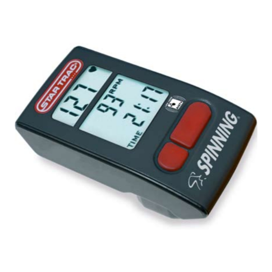
Computer Window and Buttons Start pedaling then press any button to turn on the Spinning Computer; the following data ® will be displayed: HR- Displays the Heart Rate of the user when wearing a compatible HR telemetry strap in beats per minute. - Page 11 Installing or Replacing Console Batteries Time required: • 5 Minutes Parts required: Low Battery • 4 new AA alkaline batteries Indicator Tools required: • Slotted or Phillips screwdriver NOTE: The batteries in the computer will last approximately 1 year depending on usage. The cadence sensor battery will last approximately 1 year.
-
Page 12: Installing Or Replacing Batteries
Installing or Replacing Batteries – continued 4. Note the directions each battery is to be installed. There is a plus (+) and minus (-) symbol inside the battery compartment. The + sign indicates the positive (+) side on the battery and the - indicates the negative (-) side on the battery. -
Page 13: Do I Need To Re-Sync
Do I need to Re-sync? NOTE: Syncing will not improve heart rate and is not a calibration; it should only be used to Sync (Pair up) the cadence sensor and the computer so that RPM can be transmitted. Perform the Syncing process after checking all of the following: •... -
Page 14: Testing For Rpm
Testing for RPM Time required: • Less than 5 Minutes Parts required: • N/A Tools required: • N/A TEST Procedure: 1. Once the batteries are installed, press any button and the display window will turn on in the Workout Mode. 2. -
Page 15: Syncing Mode
Syncing Mode Syncing Process: Time required: • 30 seconds Steps to Syncing: 1. Turn on computer and boot up to Workout Mode. Workout Mode window CAUTION: SYNC ONE BIKE AT A TIME; the range for the cadence sensor is approximately 30 feet and if you are testing the bike and someone else on the same room is pedaling another bike, you may be picking up the wrong RPM signal. - Page 16 Syncing Process - continued 2. Activate Sync Mode on the computer by holding down the Light and Toggle buttons for 6 seconds until the window displays “Conn“ . 3. Press the button on top of the cadence sensor. Make sure the button is depressed completely.
- Page 17 Syncing Process - continued 4. The syncing process is complete when the window on the computer displays a random ID number (e.g. ID123). 5. The computer will then automatically reboot. Wait for 5 seconds. you must wait for 5 seconds to allow the computer to reset the ID properly. 6.
-
Page 18: Setup Mode
Any time you want to change settings or view information, follow these Setup Mode steps again. To activate Setup Mode: 1. Press any button to activate computer. 2. Wave a magnet along the right side of the Spinning Computer ® until the display window switches to the Gear and Software version. - Page 19 Setup Mode - continued • Units - MILES or KM NOTE: User will not get the correct distance values if the Gear Ratio setting is not correct. (Default Setting) • BLON – (Default Back Light On*) The amount of time the backlight will stay on when the left button is pressed.
- Page 20 Setup - continued • UH – (Usage Hours) Total operation time in hours of display since the last data clearing. Press the Light (left) button to clear data, if desired, then press the Toggle (right) button to accept and advance to the next setting. o Usage hours should be reset during battery replacement.
-
Page 21: Installation Of Cadence Sensor And Magnet – All Spinners
HINT: Mount the magnet near one of the dots of the Spinning logo as shown in the figure above. ®... - Page 22 Mounting Computer On Handlebars - Spinner ® Time required: • 15 Minutes Parts required: • 727-0100 Spinning Computer Kit ® NOTE: The thick insert is used on the V-Bikes. Tools required: • 5 mm Allen Wrench • 2 mm Allen Wrench 1.
- Page 23 Mounting Computer On Handlebars - Spinner Sport / Fit / Velo ® Time required: •15 Minutes Parts required: • 727-0100 Spinning Computer Kit ® NOTE: The thin spacer is also used on the Pro 5800 / 6800 / and Elite 5900 bikes.
- Page 24 Mounting Computer On Handlebars Pro 7070 / Elite 7080 / NXT 7090 Time required: • 15 Minutes Parts required: • 727-0100 Spinning Computer Kit ® Tools required: • 5 mm Allen Wrench • 2 mm Allen Wrench 1. Install the mounting bracket to the center flat section of the handlebar by slightly prying the computer bracket clamp open.
-
Page 25: Maintenance Checklist
Maintenance Checklist Star Trac strongly recommends performing the regular daily, weekly and monthly preventive maintenance routines outlined below. If any items need replacement contact the Star Trac Customer Support Department 800-503-1221 or 714-669-1660. D= Daily W= Weekly M= Monthly Procedure Daily maintenance of the computer will determine its life of the computer by how consistently it is performed. -
Page 26: Faqs And Troubleshooting
Rider does not have the recommended chest strap or it may not be working. o Rider must keep strap within 25”- 30” (63 cm - 76 cm) of computer. • Which heart rate strap works with my Spinning Computer? ®... - Page 27 FAQs and Troubleshooting - continued • Battery light does not stay on long enough o Change the BLON time (see page 16). • No RPM o Is the magnet on the left side of the flywheel and aligned with the cadence sensor? o Sync up the computer and cadence unit and wait 60 seconds.
- Page 28 Instructor Education Cadence, Resistance And Intensity: Understanding the relationship between cadence, resistance and intensity is the key to Spinning program ® classes that meet training goals. By using the Spinner computer, you will become more proficient at increasing ® power, gaining efficient leg speed and mastering the relationship between ideal resistance and heart rate intensity.
- Page 29 Energy Zones™: The Spinning Energy Zones are the foundation of heart rate training in the Spinning program. Each Energy ® ® Zone is a type of training based on exercise intensity (indicated by heart rate). ™ Energy Zone Intensity Range Purpose ™...
- Page 30 RPM for a hill. These ranges are based on studying the cadences of elite cyclists as well as understanding how the muscles work together to turn the pedals in the most efficient manner. Cadence Range for Flat Roads: 80-110 RPM. Pedaling faster than 110 RPM is both unrealistic and counterproductive. The resistance knob on a Spinning bike ®...
- Page 31 Is It Good To Pedal Faster Than 110 RPM? Those who have a high power to resistance ratio may occasionally attain these leg speeds. This means they have the ability to overcome resistance through strength and speed. The rare, highly skilled Spinning ®...
- Page 32 It’s not dangerous to exceed 80 RPM on a hill, but for extended periods it will likely raise the rider’s intensity too high and won’t achieve the strength benefits of climbing. It is all right to exceed 80 RPM for brief periods, such as in a standing climb for the last 10-20 seconds.
- Page 33 Tips For Choosing An Appropriate Cadence And Resistance: • Warm-Up. The first ten minutes of a Spinning ride are critical for establishing proper cadence. ® With no resistance during warm-up, one may tend to pedal too quickly thus raising the heart rates prematurely.
- Page 34 The Relationship Between Cadence And Resistance: Cadence, resistance and intensity are interrelated. For any given intensity, there is a correlated cadence and resistance combination. In other words, if one knows the intensity (heart rate) he/she wants to exercise at, and selects the cadence at which to ride, he/she can find the right resistance to get to that intensity.
- Page 35 4. Find a tough climb without exceeding 85% MHR. Continue adding resistance until one feels the need to rise out of the saddle in a standing climb. (Outdoors, cyclists stand on a climb when the road becomes steeper.) Maintain a cadence of 70–75 RPM. Play with these three variables, finding the right combination to meet the parameters.
- Page 36 Next, add a little hill while maintaining the same intensity. Remain seated and ride a progressively steeper hill by gradually adding resistance every 3-4 minutes. Try to maintain the same intensity of 80%. In order to do so, one will have to slow his/her legs down as the hill becomes steeper. Ride at 80, 75, 70, 65 and 60 RPM. If one cannot maintain the intensity he/she should ride at the last cadence where he/she could.
- Page 37 Ladders: Ladders are a progressive increase or decrease in one of the following variables: cadence, resistance or intensity. This drill is best employed using seated or standing flats and seated or standing climbs. Jumps do not work well for ladders. One can use a combination of the following drills in any profile: •...
- Page 38 Next, try this over 60 seconds, raising the cadence 2 RPM every 4 seconds. Seated Climbs: Climb at 60 RPM with enough resistance to bring the intensity to 75%. Gradually increase the cadence to 80 RPM over 60 seconds. If possible, use 85% MHR as a ceiling. One may have to try this several times to find a hill that allows him/her to stay within the desired intensity.
- Page 39 This page intentionally left blank...
- Page 40 Spinning Ride Profile: ® This Strength Energy Zone ride takes a rider on three hills, each one a little longer, steeper and therefore more ™ difficult. For the first hill, attempt to keep the heart rate at 80% max. Allow heart rate to rise to 85% with the second and third hills.
- Page 41 Elapsed Time Duration Movement/Cadence Intensity Technique 20:00 – 23:00 5 min Seated Flat 75% MHR Unload resistance and increase ca- 90-100 RPM dence to 90-100 RPM. Find the right resistance to maintain a heart rate effort at 75%. 23:00 – 35:00 12 min Seated Climb 80-85 MHR...
- Page 42 This page intentionally left blank...
- Page 43 This page intentionally left blank...
- Page 44 Spinning Computer Manual ® 620-7654 Rev H ©2009 Star Trac. All Rights Reserved. Star Trac and the Star Trac logo are registered trademarks of Unisen, Inc. Expect Different is a trademark of Unisen, Inc. SPIN , Spinning , Spinner , the ®...
Need help?
Do you have a question about the Spinning Computer and is the answer not in the manual?
Questions and answers