
Related Manuals for Star Trac Star Trac Fitness Spinning Computer

Summary of Contents for Star Trac Star Trac Fitness Spinning Computer
- Page 1 Star Trac Fitness™ Spinning Computer ® User Manual Installation, Service and Instructor Education...
-
Page 3: Table Of Contents
Table of Contents FCC Regulatory Statements _________________________________________________ Parts List _______________________________________________________________ Marketing Statement Regarding Heart Rate ____________________________________ Specifications ____________________________________________________________ How it Works ____________________________________________________________ Computer Window and Buttons ______________________________________________ Installing or Replacing Batteries______________________________________________ Do I need to Re -sync? _____________________________________________________ Testing for RPM _________________________________________________________ Syncing Mode ___________________________________________________________ Setup Mode_____________________________________________________________ Installation of Cadence Sensor and Magnet –... -
Page 4: Fcc Regulatory Statements
(1) this device may not cause harmful interference, and (2) this device must accept any interference received, including interference that may cause undesired operation. 2. Changes or modifications not expressly approved by Star Trac could void the user’s authority to operate the equipment. -
Page 5: Parts List
Parts List ® All 727-0083 Spinning Computer Kits include: Part Number for Description re-order ntity 727-0083 ® Spinning ® Spinning Computer Computer Kit Mounting Bracket 727-0093-KT Mounting V2 Bracket Mounting Insert Bracket Kit Pro Bracket Mounting Insert 727-0084-KT Cadence Sensor 727-0094 Cadence Magnet AA Panasonic Batteries... -
Page 6: Marketing Statement Regarding Heart Rate
Trac takes the acquisition and accuracy of heart rate very seriously and has developed a system to erform to the best ability that technology will allow. Star Trac has engineered a product that has taken very precaution possible to acquire an accurate heart rate signal as well as eliminate “crosstalk”... - Page 7 3) Riders must lean into the display (within 16 inches) and wait for the HR to display – once the HR is displayed they must maintain the forward Position for 15 seconds while the computer codes with their Polar Coded Strap, this insures that no outside signals will interfere with the riders data once they lean back into their seated position.
-
Page 8: Specifications
Specifications Computer: Heart Rate Range: Approximately 30” From computer to users HR chest strap Battery: Qty 4 each AA Alkaline Battery life expectancy: 1 year (depending on use and backlight usage) Cadence Sensor: Battery: Lithium CR2032 Battery life expectancy: Approximately 2.5 Years (depending on use) Distance to magnet: Approximately 5mm... -
Page 9: How It Works
How it Works How does the Spinning computer work? he Spinning computer displays heart rate, RPM (speed), total distance and elapsed time. © © © The heart rate information is received from a Polar T61, Polar T31C or Polar ® WearLink heart rate strap worn by the person riding the Spinning Bike. -
Page 10: Computer Window And Buttons
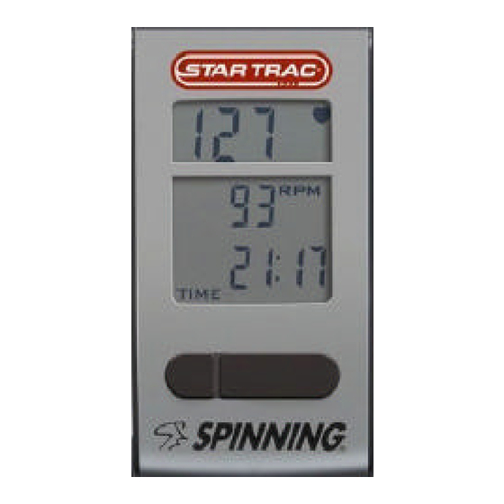
Computer Window and Buttons ® tart pedaling then press any button to turn on the Spinning Computer; the following data will be splayed: ® HR- Displays the Heart Rate of the user when wearing a compatible Polar telemetry strap in beats per minute. RPM- Shows the pedaling speed of the user in revolutions per minute. -
Page 11: Installing Or Replacing Batteries
Installing or Replacing Batteries me required: 5 Minutes arts required: Low Battery Indicator 4 new AA alkaline batteries ools required: Slotted or Phillips screwdriver ote: The batteries in the computer will last approximately year depending on usage. he cadence sensor battery will last approximately 2.5 Remove the computer from the handlebar or computer mounting bracket. - Page 12 Installing or Replacing Batteries – cont’d Note the directions each battery is to be installed. There is a plus (+) and minus (-) symbol inside the battery compartment. The + sign indicates the positive (+) side on the battery and the - indicates the negative (-) side on the battery.
-
Page 13: Do I Need To Re-Sync
Do I need to Re-sync? : Syncing will not improve Heart Rate and is not a calibration it should only be used to Sync Pair up) the cadence sensor and the computer so that RPM can be transmitted. erform the Syncing process after checking all of the following: Do the serial numbers on the cadence sensor and the computer match? If they do not match the handlebar has been swapped... -
Page 14: Testing For Rpm
Testing for RPM me required: Less then 5 Minutes arts required: ools required: TEST Procedure: Once the batteries are installed, press any button and the display window will turn on in the Workout mode. Test by waving a magnet across the cadence sensor. If you see RPM values, then the cadence sensor and computer was synced successfully, there is no need to perform the sync process. -
Page 15: Syncing Mode
Syncing Mode yncing Process: ools required: Coin (penny, dime, etc.) or similar item to remove battery cover teps to Syncing: ® Removing the battery lid on the backside of the Spinning Computer and insert or replace th 4 AA batteries. 2. - Page 16 Syncing Process – cont’d 4. Place the battery back in the cadence upside down to reset the system. Do not put the lid back on yet. Battery facing Battery facing upside down right side up Sync 5. Activate Sync Mode on the computer by holding down the Light Mode and Toggle buttons for several seconds until the window displays window...
- Page 17 Syncing Process – cont’d 8. With the computer window still displaying “Conn” hold the magnet about 1/2 inch (1.2 cm) away from the edge of the cadence sensor with the large arrow pointing towards the magnet. Wave the magnet back and forth several times until the window on the computer displays a random ID number (e.g.
-
Page 18: Setup Mode
Setup Mode ® Spinning Computer is pre-set with a gear ratio 2 and a setting display distance in miles. It is so pre-set with recommended default settings for the length of time the backlight will stay on when ctivated and the length of time summary information will be displayed. You can make changes to ese settings by following the steps below. - Page 19 Setup Mode- cont’d Units - MILES or KM Note: User will not get the correct RPM values if the Gear Ratio setting is not correct. (Default Setting) BLON – (Default Back Light On*) The amount of time the backlight will stay on when the left button is pressed. Select between 1 second to 60 seconds using the Light (left) button and press the Toggle (right) button to save and advance to the next setting.
- Page 20 Setup Mode- cont’d UH – (Usage Hours) Total operation time in hours of display since the last data clearing. Press the Light (left) button to clear data, if desired, then press Toggle (right) button to accept and advance to the next setting. ODO –...
-
Page 21: Installation Of Cadence Sensor And Magnet - All Spinners
Installation of Cadence Sensor and Magnet – All Spinners® Before the cadence sensor is securely fastened to the flywheel support, it must be adjusted so that it is about 5 mm (.20 in) from the magnet face. Install the magnet on the flywheel so that it aligns with the arrow on the end of the cadence sensor. -
Page 22: Mounting Computer On Handlebars - V-Bikes
Mounting Computer On Handlebars - V-Bikes me required: 15 Minutes arts required: ® 727-0083 Spinning Computer Kit NOTE: The thick insert is used on the V-Bikes ools required: M5 Allen Wrench M2 Allen Wrench Place the thick insert inside the bottom part of the Mounting Bracket Clamp. -
Page 23: Mounting Computer On Handlebars - Pro 5800 / 6800 / Elite 5900
Mounting Computer On Handlebars - Pro 5800 / 6800 / Elite 5900 me required: 15 Minutes arts required: ® 727-0083 Spinning Computer Kit Note: The thin spacer is used on Pro 5800 / 6800 and Elite 5900 bikes. ools required: M5 Allen Wrench M2 Allen Wrench Place the thin insert inside the bottom part of the... -
Page 24: Mounting Computer On Handlebars - Elite 6900 And Nxt 7000
Mounting Computer On Handlebars - Elite 6900 and NXT 7000 me required: 15 Minutes arts required: 727-0083 Spinning® Computer Kit Note: The inserts and mounting bracket are not used on the Elite 6900 or NXT 7000. ools required: M5 Allen Wrench M2 Allen Wrench 1. - Page 25 FAQ’s and Troubleshooting tar Trac strongly recommends performing the regular daily, weekly and monthly preventive aintenance routines outlined below. If any items need replacement contact the Star Trac Custome upport Department at 800-503-1221 or 1-714-669-1660. Daily W= Weekly M= Monthly...
- Page 26 Press any button. Pedal the bike and then press any button. Check batteries in computer. No heart rate ® Is the user wearing a Polar “Coded” HR chest strap? Moisten the strap and wear it against the skin. The battery in the strap might be low, try another strap. Stay in Syncing position for 15 seconds.
-
Page 27: Faq's And Troubleshooting
FAQ’s and Troubleshooting – cont’d Battery light does not stay on long enough Change the BLON time (see page 6). No RPM Is the magnet on the left side of the flywheel and aligned with the cadence sensor Sync up the computer and cadence unit and wait 60 seconds. Check the battery in the cadence sensor. -
Page 28: Spinning® Instructor Education
Spinning® Instructor Education Instructor Education adence, Resistance And Intensity: nderstanding the relationship between cadence, resistance and intensity is the key to Spinning® ogram classes that meet training goals. By using the Spinner® computer, you will become more oficient at increasing power, gaining efficient leg speed and mastering the relationship between eal resistance and heart rate intensity. - Page 29 nergy Zones™: he Spinning Energy Zones are the foundation of heart rate training in the Spinning® program. Each nergy Zone™ is a type of training based on exercise intensity (indicated by heart rate). Energy Zone™ Intensity Range Purpose covery 50% to 65% of MHR Relaxation and energy accumulation.
- Page 30 CADENCE FUNDAMENTALS What Is Cadence? adence is defined as the number of times the pedals revolve per minute, also known as RPM f volutions per minute. The safest, most efficient and most realistic cadences are 80–110 RPM for a at road and 60–80 RPM for a hill. These ranges are based on studying the cadences of elite cyclist s well as understanding how the muscles work together to turn the pedals in the most efficient anner.
- Page 31 It Good To Pedal Faster Than 110 RPM? hose who have a high power to resistance ratio may occasionally attain these leg speeds. This eans they have the ability to overcome resistance through strength and speed. The rare, highly killed Spinning® enthusiast (often cyclists) who have mastered a smooth pedal stroke and who nderstand the dynamics of cadence can pedal faster than 110 rpm for 1-3 minutes.
- Page 32 s not dangerous to exceed 80 RPM on a hill, but for extended periods it will likely raise the rider’s tensity too high and won’t achieve the strength benefits of climbing. It is all right to exceed 80 RPM r brief periods, such as in a standing climb for the last 10-20 seconds. The rider intensity will crease dramatically, so make sure one has planned for this in his/her profile.
- Page 33 ps For Choosing An Appropriate Cadence And Resistance: Warm-Up. The first ten minutes of a Spinning ride are critical for establishing proper cadence. With no resistance during warm-up, one may tend to pedal too quickly thus raising the heart rates prematurely. During the warm-up, it’s important to work on cadence by keeping intensity under control (65% or less).
- Page 34 Relationship Between Cadence And Resistance: adence, resistance and intensity are interrelated. For any given intensity, there is a correlated adence and resistance combination. In other words, if one knows the intensity (heart rate) he/she to exercise at, and selects the cadence at which to ride, he/she can find the right resistance to et to that intensity.
- Page 35 4. Find a tough climb without exceeding 85% MHR. Continue adding resistance until one feels the need to rise out of the saddle in a standing climb. (Outdoors, cyclists stand on a climb when the road becomes steeper.) Maintain a cadence of 70–75 RPM. Play with these three variables, finding the right combination to meet the parameters.
- Page 36 ext, add a little hill while maintaining the same intensity. Remain seated and ride a progressively eeper hill by gradually adding resistance every 3-4 minutes. Try to maintain the same intensity of 0%. In order to do so, one will have to slow his/her legs down as the hill becomes steeper. Ride at 0, 75, 70, 65 and 60 RPM.
- Page 37 adders: adders are a progressive increase or decrease in one of the following variables: cadence, resistanc intensity. This drill is best employed using seated or standing flats and seated or standing climbs. umps do not work well for ladders. One can use a combination of the following drills in any profile: Constant cadence with increasing resistance in a seated flat or standing flat.
- Page 38 ext, try this over 60 seconds, raising the cadence 2 RPM every 4 seconds. eated Climbs: Climb at 60 RPM with enough resistance to bring the intensity to 75%. Gradually crease the cadence to 80 RPM over 60 seconds. If possible, use 85% MHR as a ceiling. One may ave to try this several times to find a hill that allows him/her to stay within the desired intensity.
- Page 39 This page intentionally left blank...
- Page 40 pinning® Ride Profile: his Strength Energy Zone™ ride takes a rider on three hills, each one a little longer, steeper and erefore more difficult. For the first hill, attempt to keep the heart rate at 80% max. Allow heart rate rise to 85% with the second and third hills.
- Page 41 23:00 3 min Seated Flat 75% MHR Unload resistance and increase cadence to 90 90-100 . Find the right resistance to maintain a heart rate effort at 75%. 35:00 12 min Seated Climb 80-85 MHR Add resistance to moderat e /heavy and combine al 60-80 three movements in any combination.
- Page 42 This page intentionally left blank...
- Page 43 This page intentionally left blank...
- Page 44 800-503-1221 http://support.startrac.com/ For more information on Spinning® education, events, accessories and apparel log onto www.spinning.com Spinning® Computer Manual 620-7654 Rev F...
Need help?
Do you have a question about the Star Trac Fitness Spinning Computer and is the answer not in the manual?
Questions and answers