Table of Contents
Advertisement
Service and
Maintenance
User Manual
This manual must be read carefully before using your Boss Industries Inc. Air Com-
pressor. Store in a safe and convenient location for future reference.
For technical support:
Phone: (800) 635-6587 (USA)
Phone: (219) 324-7776 (Outside USA)
Fax: (877) 254-4249 (USA)
Email: service@bossair.com
Website: http://www.bossair.com
Engine Driven
Air Compressor
01/09/2012 DCL
309003
Advertisement
Table of Contents

Related Manuals for Boss Industries Bullet 2


Summary of Contents for Boss Industries Bullet 2
- Page 1 Maintenance Engine Driven User Manual Air Compressor This manual must be read carefully before using your Boss Industries Inc. Air Com- pressor. Store in a safe and convenient location for future reference. For technical support: Phone: (800) 635-6587 (USA) Phone: (219) 324-7776 (Outside USA) Fax: (877) 254-4249 (USA) Email: service@bossair.com...
- Page 2 309003...
-
Page 3: Table Of Contents
Contents Manual Change History....................5 1.1 Revision List....................5 Welcome........................6 2.1 General Information..................6 2.2 Overview ......................6 Safety........................7-9 3.1 General Safety Overview..................7 3.2 Safety Precautions...................8-9 Specifications......................10 4.1 Specification Sheet..................10 Description of Components................11-12 5.1 Engine......................11 5.2 Drive System....................11 5.3 Compressor Airend..................11 5.4 Separator System..................11 I. - Page 4 8.5 Blowdown Valve................24 8.6 Engine Overheating................24 8.7 Oil Consumption.................24 8.8 Coalescer Plugging................25 8.9 High Compressor Discharge Temperature..........25 8.10 Contacting Boss Industries Inc..............25 Warranty.....................26-31 9.1 Warranty Statement................27 9.2 Summary of Main Warranty Provisions..........28 9.3 Return Goods Instructions..............29 9.4 Preparation of Part Return..............29 9.5 Filing Procedures................29...
-
Page 5: Manual Change History
Revision List 1.1 Revision List s t r . t s c i f i t a t i t l 309003... -
Page 6: Welcome
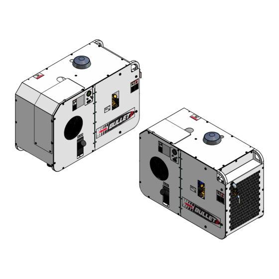
04/7/2011 DCL 2.2 Overview The Boss Industries Inc. Bullet 2 is a compact, strategically designed system. It integrates all major components on a single frame, which is enclosed in a tough, weather-resistant canopy. The Bullet 2 design provides output of up to 70 CFM (cubic feet of air per minute) at up to a maximum of 100 PSI (pounds per square inch). -
Page 7: Safety
Boss Industries Inc. expressly disclaims responsi- bility or liability for any injury or damage caused by failure to observe these specified precautions or by failure to exercise the ordinary caution and due care required while operating or handling this equipment, even though not expressly specified. -
Page 8: Safety Precautions
Safety 2.1 Safety Precautions The following safety precautions are a general guide to safe operation of the equipment. Read and understand the operations manual and all other safety instructions before using this equipment. Failure to follow operating instructions and/or failure to follow maintenance proce- dures and intervals could result in personal injury, death, and/or damage to equipment and property. -
Page 9: Safety
When using tools, maintain secure footing at all times. Do not overreach or awkwardly use air tools. Use only Boss Industries Inc. approved replacement parts or equivalent. Over-tensioning belts will cause premature belt, bearing, and shaft seal failure. -
Page 10: Specifications
Specifications 4.1 Specification Sheet ° 0 ° 0 & ° 2 " 4 i t l t l i i t l SPECIFICATIONS SUBJECT TO CHANGE WITHOUT PRIOR NOTICE 3.44 30.00 45.00 3.94 2.52 20.00 2.51 0.44 4-PLACES 16.50 37.13 309003... -
Page 11: Description Of Components
Description of Components 5.1 Engine The Bullet 2 air compressor contains a Subaru EH72 4-cycle, v-twin, OHV, air cooled, gasoline engine. This engine has been specially selected to handle the rugged duty required for its operation. This engine is setup to run on standard unleaded gasoline. The engine speed is modulated by a pneumatically controlled cylinder piloted by the compressor regulator. -
Page 12: Pressure Relief Valve
The fuel tank is an E.P.A. and C.A.R.B. certified tank that hold 5 gallons of gasoline. Carbon Canister The Bullet 2 is equipped with a carbon canister that filters the gasoline vapors from the fuel tank before they are directed back to the engine carburator. -
Page 13: Installation & Operation
Do not modify this compressor except with written factory approval. 6.2 Lifting Boss Industries Inc. offers a lifting bail option for routine lifting, loading onto trucks, etc. Compressors to be air lifted by helicopter must not be supported by the lifting provision, but by slings with appropriate spreader bars. -
Page 14: Mounting The Compressor
Installation & Operation 6.3 Mounting the Compressor When mounting the compressor care should be taken to ensure that its location does not impede the operation of other components on the vehicle. For example, if your vehicle is equipped with a crane, you must make sure the compressor will not interfere with the swing of the crane. -
Page 15: Machine Documentaion
Installation & Operation 6.6 Machine Documentation Record all serial numbers for this installation. A. Boss Industries Inc. Serial Number ___________________________________________________________________________ B. Engine Serial Number ___________________________________________________________________________ C. Compressor Serial Number ___________________________________________________________________________ D. Note any special applications relating to specific installations. ___________________________________________________________________________ 6.7 Operating Procedure... -
Page 16: Operating Conditions
Installation & Operation 6.7 Operating Procedure I. Read the operation section in the manual carefully before proceeding onto the initial start-up. II. Verify the service valve is closed. III. Pull the choke cable and start the engine. If the engine is warm or the ambient temperature is high, pull the choke knob half-way, or keep it fully open. -
Page 17: Maintenance
Maintenance 7.1 Overview This section contains instructions for performing the inspection, lubrication, and maintenance proce- dures required to maintain the compressor in proper operating condition. The importance of per- forming the maintenance described herein cannot be over emphasized. The periodic maintenance procedures to be performed on the equipment covered by this manual are listed on the following page. -
Page 18: Maintenance Chart
Maintenance 7.4 Maintenance Chart The MAINTENANCE CHART lists serviceable items on this compressor package. The items are listed according to their frequency of maintenance, followed by those items which need only “As Required” maintenance. INTERVAL DESCRIPTION Check sump tank oil level. EVERY 10 HOURS OR Check for leaks. -
Page 19: Compressor Oil
Boss Industries Inc. rotary screw lubricant. The lubricant supplier’s recommendation must, therefore, be based upon not only the following general characteristics, but also upon his own knowledge of the suitability of the recommended lubricant in helical screw type air compressors operating in the particular environment involved. -
Page 20: Compressor Oil Fill, Level, And Drain
Maintenance Due to environmental factors, the useful life of all “extended life” lubricants may be shorter than quoted by the lubricant supplier. Boss Industries Inc. encourages the user to closely monitor the lubricant condition and to participate in an oil analysis program with the supplier. No lubricant, however good and/or expensive, can replace proper maintenance and attention. -
Page 21: Belt Tensioning Procedure
Maintenance 7.8 Belt Tensioning Procedure I. Be sure unit is off and key is removed. II. Use 3/4” socket to turn the compressor slide plate adjustment bolt clockwise to tighten the compressor belts. Over-tensioning belts will cause premature belt, bearing, and shaft seal failure. -
Page 22: Troubleshooting
Troubleshooting 8.1 Overview This section contains instructions for troubleshooting the equipment following a malfunction. The troubleshooting procedures to be performed on the equipment are listed below. Each symptom of trouble for a component or system is followed by a list of probable causes of the trouble and suggested procedures to be followed to eliminate the cause. -
Page 23: Unplanned Shutdown
Troubleshooting 8.3 Unplanned Shutdown When the operation of the machine has been interrupted by an unexplained shutdown, check the following: I. Check to determine if compressor oil is at proper level. II. Check oil cooler for dirt, slush, ice on the fins, or any other obstructions to cooling airflow. III. -
Page 24: Blowdown Valve
Troubleshooting 8.5 Blowdown Valve If after the compressor is shutdown, pressure does not automatically blow-down, check for: I. Automatic blow down valve may be inoperative. II. Blockage in air line from blow down valve to coalescer head. III. Orifice at blow down clogged. 8.6 Engine Overheating I. -
Page 25: Coalescer Plugging
IV. Clean oil system (cooler) internally. V. Plugged compressor oil filter. Change element. VI. Plugged oil return line, clean orifice and check valve. 8.10 Contacting Boss Industries Inc. Phone: (800) 635-6587 (USA) Phone: (219) 324-7776 (Outside USA) Fax: (877) 254-4249 (USA) Email: service@bossair.com... - Page 26 309003...
-
Page 27: Warranty Statement
WARRANTY SECTION 309003... -
Page 28: Warranty
Warranty 9.1 Warranty Policy Boss Industries, Inc. (BOSS) warrants that this Rotary Screw Compressor unit conforms to applicable drawings and specifications approved in writing by BOSS. The unit assembly will be free from defects in material and workmanship for a period of three (3) years from the date of initial operation or forty-two (42) months from the date of shipment, whichever period first expires. -
Page 29: Summary Of Main Warranty Provisions
Warranty 9.2 Summary of Main Warranty Provisions As claims, policies and procedures are governed by the terms of the BOSS Industries, Inc. (BOSS) warranty, it is necessary to outline some of the more important provisions. The BOSS warranty applies only to new and unused products, which, after shipment from the factory, have not been altered, changed, repaired or mistreated in any manner whatsoever. -
Page 30: Filing Procedures
4. Claim denial will result in issuance of a letter of denial. 5. BOSS INDUSTRIES will consider each claim on its’ own merit and reserves the right to accept or reject claim request. In case of air-ends, these will be returned to the manufacturer for their analysis/ input. -
Page 31: Claims Provisions
5. Machine is within warranty period. 6. Machine has been operated within design conditions. Claims made through distributors must be verified by distributor prior to contacting BOSS INDUSTRIES. 9.7 Damage in Transit Do not return damaged merchandise to BOSS INDUSTRIES, please follow claim procedure. -
Page 32: Airend Exchange Program
9.8 Screw Compressor Airend Exchange Program Replacement air-ends are available from the factory. For current prices and availability, contact BOSS INDUSTRIES, Inc. or an authorized BOSS INDUSTRIES distributor. Prices are F.O.B. shipping point. Prices do not include labor for removal or installation. -
Page 33: Drawings
PARTS AND ILLUSTRATION SECTION 309003... -
Page 34: Frame System
Frame System 10.1 Frame System Parts List ITEM PART NUMBER DESCRIPTION 300907 BATTERY 80241 TANK 308035 AIR FILTER 302207 BAND 302204 308957 BRACKET 308936 FRAME 305160 GAUGE 300339-060 CABLE 120-36992 INSERT 929104-075 BOLT 938604-071 WASHER 300853 INDICATOR 960702-012 ELBOW 960402-012 NIPPLE 901215-005 COUPLING... - Page 35 Frame System 10.1 Frame System (continued) 309003...
-
Page 36: Engine System
Engine System 10.2 Engine System Parts List ITEM PART NUMBER DESCRIPTION 300807-005 PULLEY 300745-112 BUSHING 308963 ENGINE 929806-200 BOLT 938206-071 WASHER 925506-198 992114-025 ADAPTER 922104-020 NIPPLE 901515-010 ELBOW 900000-010 PLUG 309003... - Page 37 Engine System 10.2 Engine System (continued) 309003...
-
Page 38: Compressor System
Compressor System 10.3 Compressor System Parts List ITEM PART NUMBER DESCRIPTION 938908-180 WASHER 938808-200 WASHER 301594 DECAL 308877 PLATE 308999 BOLT 937808-125 WASHER 925508-262 929208-250 BOLT 302203 VALVE 308040 ADAPTER 301709 AIREND 301786-250 CLAMP 929208-300 BOLT 302467 GASKET 970804-025 ADAPTER 960216-100 ELBOW 970816-100... - Page 39 Compressor System 10.3 Compressor System (continued) 309003...
-
Page 40: Cooler System
Cooler System 10.4 Cooler System Parts List ITEM PART NUMBER DESCRIPTION 961908-050 960208-050 ELBOW 943104-038 RIVET 929705-100 BOLT 961505-140 308956 SHROUD 300424 COOLER 960108-050 CONNECTOR 302865 SENSOR 302253 FAN ASSY 309003... - Page 41 Cooler System 10.4 Cooler System (continued) 309003...
-
Page 42: Sump Tank System
Sump Tank System 10.5 Sump Tank System Parts List ITEM PART NUMBER DESCRIPTION 300741 SUMP 300343 BAND 922216-000 NIPPLE 300783 SIGHTGLASS 960016-100 ELBOW 902915-040 PLUG 300330-200 VALVE 960616-100 902915-010 PLUG 960212-075 ELBOW 902715-020 300599 HEAD 300005 ELEMENT 960208-075 ELBOW 961612-050 NIPPLE 922208-000 NIPPLE... - Page 43 Sump Tank System 10.5 Sump Tank System (continued) 309003...
-
Page 44: Canopy System
Canopy System 10.6 Canopy System Parts List ITEM PART NUMBER DESCRIPTION 308961 PANEL 308959 PANEL 981504-075 SCREW 984004-071 WASHER 977004-062 WASHER 308996 DECAL 308995 DECAL 302568 DECAL 300042 DECAL 300040 DECAL 300039 DECAL 300515 DECAL 308962 PANEL 308988 PANEL 120-36992 INSERT 309014 PANEL... - Page 45 Canopy System 10.6 Canopy System (continued) 309003...
-
Page 46: Coalescer System
Coalescer System 10.7 Coalescer System Parts List ITEM PART NUMBER DESCRIPTION 970812-075 ADAPTER 907603-010 BUSHING 902415-030 922212-000 NIPPLE 901515-030 ELBOW 992008-025 CONNECTOR 977604-025 ELBOW 987204-025 CONNECTOR 308970 TUBE 300022-075 VALVE 308974 HEAD 929210-200 BOLT 938810-220 WASHER 938910-200 WASHER 970612-075 ELBOW 309402 ORIFICE 922112-020... - Page 47 Coalescer System 10.7 Coalescer System (continued) 309003...
-
Page 48: Wiring Diagram
Wiring Diagram 10.8 Wiring Diagram 309003... -
Page 49: System Schematic
System Schematic 10.9 System Schematic 309003...
Need help?
Do you have a question about the Bullet 2 and is the answer not in the manual?
Questions and answers