Sign In
Upload
Download
Table of Contents
Contents
Add to my manuals
Delete from my manuals
Share
URL of this page:
HTML Link:
Bookmark this page
Add
Manual will be automatically added to "My Manuals"
Print this page
×
Bookmark added
×
Added to my manuals
Manuals
Brands
EnGenius Manuals
Switch
EGS2108P
User manual
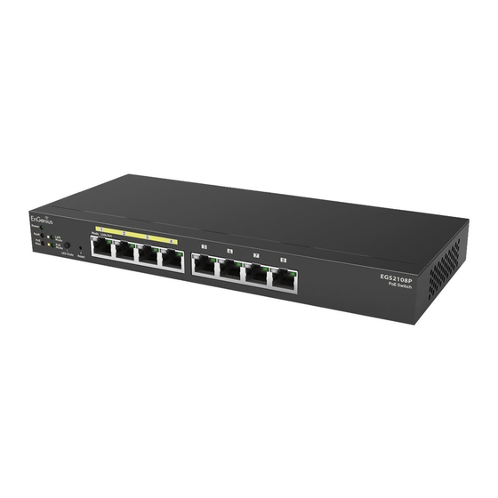
EnGenius EGS2108P User Manual
Egs smart switch series 8-port gigabit switches
Hide thumbs
Also See for EGS2108P
:
User manual
(48 pages)
1
2
Table Of Contents
3
4
5
6
7
8
9
10
11
12
13
14
15
16
17
18
19
20
21
22
23
24
25
26
27
28
29
30
31
32
33
34
35
36
37
38
39
40
41
42
43
44
45
46
page
of
46
Go
/
46
Contents
Table of Contents
Bookmarks
Table of Contents
Table of Contents
Chapter 1 Product Overview
Introduction/Package Contents
Technical Specifications
Physical Interface
Management Interface
Connecting the Switch to a Network
Web Access
Chapter 2 Management
System
IP Setting
Port Settings
Poe Management
Poe Port Configuration
Cable Diagnostics/Password
Zero Configuration
L2 Feature
Port Trunking
IGMP Snooping/Multicast Group List
Port Mirroring
Loopback Detection
Static MAC Address/Dynamic Address List
Vlan
802.1Q
Pvid
Port-Based VLAN
Qos
802.1P Default Priority
Cos Priority Class
Storm Control
Bandwidth Control
Chapter 3 Maintenance
Maintenance
Upgrading/Resetting
Rebooting/Logging out
Appendix
FCC Interference Statement
Federal Communication Commission Interference Statement
IC Interference Statement
CE Interference Statement
Advertisement
Quick Links
1
Introduction/Package Contents
2
Technical Specifications
3
Physical Interface
4
Management Interface
5
Connecting the Switch to a Network
6
System
7
Ip Setting
8
Upgrading/Resetting
Download this manual
Business Solutions
User Manual
EGS2108P
|
EGS2110P
|
EGS5110P
version 1.0
EGS Smart Switch Series
8-Port Gigabit Switches
Table of
Contents
Previous
Page
Next
Page
1
2
3
4
5
Advertisement
Table of Contents
Need help?
Do you have a question about the EGS2108P and is the answer not in the manual?
Ask a question
Questions and answers
Related Manuals for EnGenius EGS2108P
Switch EnGenius EGS5110P User Manual
8-port gigabit poe+ smart switch with 2 gigabit sfp (48 pages)
Switch EnGenius EGS2110P User Manual
Egs smart switch series 8-port gigabit switches (46 pages)
Switch EnGenius EGS7228P User Manual
Neutron series layer 2 managed poe+ switch (151 pages)
Switch EnGenius EGS5212FP User Manual
Neutron series layer 2 managed poe+ switch (151 pages)
Switch EnGenius EGS5212FP Quick Installation Manual
(3 pages)
Switch EnGenius EGS7228FP User Manual
Neutron series layer 2 managed poe+ switch (151 pages)
Switch EnGenius EGS7252FP User Manual
Neutron series layer 2 managed poe+ switch (151 pages)
Switch EnGenius EWS5912FP User Manual
Neutron series wireless management switch (207 pages)
Switch EnGenius EWS7928P Product Setup
Wms 24-port gigabit poe+ l2 switch (9 pages)
Switch EnGenius EWS2910P User Manual
Ews wireless management (60 pages)
Switch EnGenius EWS Series User Manual
Gigabit managed smart switch with wireless controller (207 pages)
Switch EnGenius EWS1200-28T User Manual
Gigabit managed smart switch with wireless controller (207 pages)
Switch EnGenius EWS1200D-10T User Manual
Gigabit managed smart switch with wireless controller (207 pages)
Switch EnGenius EWS1200-52T User Manual
Gigabit managed smart switch with wireless controller (207 pages)
Switch EnGenius EWS2910P-FIT Quick Start Manual
Managed 55w poe+ switch (10 pages)
Switch EnGenius EWS7952P-FIT Quick Start Manual
Fit l2+ managed 410w poe+ switch (10 pages)
This manual is also suitable for:
Egs2110p
Egs5110p
Egs series
Table of Contents
Print
Rename the bookmark
Delete bookmark?
Delete from my manuals?
Login
Sign In
OR
Sign in with Facebook
Sign in with Google
Upload manual
Upload from disk
Upload from URL


Need help?
Do you have a question about the EGS2108P and is the answer not in the manual?
Questions and answers