Advertisement
Table of Contents
- 1 Table of Contents
- 2 Camera Kit Contents
- 3 VL1 Overview
- 4 Definition
- 5 Mounting the Camera
- 6 Camera Setup - Getting Started
- 7 Setting the MODE of Your VL1
- 8 Driver and Ulead Photo Explorer Installation
- 9 Viewing Images Via PC or Digital Camera
- 10 Web Cam Mode
- 11 Web Cam Software and Enhanced Security
- 12 Technical Specifications
- 13 General Information and Safety
- 14 CE and ROHS Compliance
- Download this manual
See also:
Manual
Advertisement
Table of Contents

Subscribe to Our Youtube Channel
Related Manuals for Securesight VL1

Summary of Contents for Securesight VL1
- Page 1 User’s Manual Version 1.5 Sept 07...
-
Page 2: Table Of Contents
B. VL1 overview C. Definition D. Mounting the camera E. Camera setup – Getting started F. Setting the MODE of your VL1 G. Driver and Ulead Photo Explorer installation H. Viewing images via PC or digital camera I. Web Cam Mode J. -
Page 3: Camera Kit Contents
A. Camera kit contents • Model VL1 Lighting Camera • 512Mb SD card • USB lead • Ulead Photo Explorer software and camera driver CD • User Manual © Securesight 2007 E&OE... -
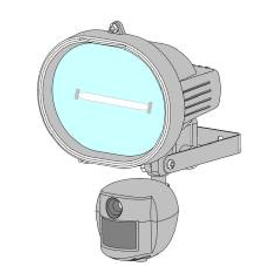
Page 4: Vl1 Overview
B. VL1 overview Front view © Securesight 2007 E&OE... - Page 5 Base view © Securesight 2007 E&OE...
-
Page 6: Definition
Halogen lamp: For lighting purpose, please use the correct voltage and wattage of halogen light for this product. Halogen lamp R7S, Max power: 500W. • Bracket: For mounting the VL1. • AC cable outlet: For connecting the external AC cable to VL1. - Page 7 Lux control knob: For adjusting the ambient lighting level at which the floodlight will come on automatically. • USB socket: For connecting the VL1 to a PC with the USB lead provided. • SD slot: For inserting a SD memory card. Ensure card firmly pushed in.
- Page 8 3. Definition of Control display. © Securesight 2007 E&OE...
- Page 9 : Image counter to show how many images or videos have been captured. • : Storage status icon. Only present if an external SD card installed. If no icon your VL1 will use its internal built memory. • : Video-capturing icon. Indicates your VL1 is in video capturing mode and will capture 10 second video bursts.
- Page 10 : Low-resolution icon. Indicates the VL1 is in low- resolution still image capturing mode. • D: Date setting mode. Indicates when your VL1 is in Date setting mode. • T: Time setting mode. Indicates when your VL1 is in Time setting mode.
- Page 11 4. Picture / Image Capacity High 2.0M Low 1.3M AVI QVGA SD card 1600x1200 1280x1024 320x240 Built In memory 16MB 32MB 64MB 128MB 256MB 512MB 1280 1664 2560 © Securesight 2007 E&OE...
- Page 12 These figures may vary depending on the amount of detail in the image. Also, when your memory card is full, your VL1 will begin overwriting the earliest data ensuring you always have the most recent images.
-
Page 13: Mounting The Camera
D. Mounting the camera Mount the VL1 to a solid surface more than ½” thick in a secure location overseeing the area to monitor. We suggest you mount the camera between 2 and 4 meters off the ground with the camera pointing at a downward angle. -
Page 14: Camera Setup - Getting Started
• Your VL1 is supplied with a 512Mb SD card. Insert the SD memory card in to the SD card slot completely and in the correct direction as shown on the inside of the housing. - Page 15 © Securesight 2007 E&OE...
- Page 16 • Ensure you connect your VL1 in accordance with the wiring diagram. Failure to do so may result in damage to your VL1 and will void your warranty. • We recommend using a supply that you can switch off if required.
- Page 17 High High/Low Image capture method Video Video/Photo Floodlight control On/Off Your VL1 can be used straight away but before use you may wish to change some or all of the settings – see the next sections. © Securesight 2007 E&OE...
- Page 18 3. Set the Data and Time. • After mounting your VL1 (with SD card already fitted if required) connect the camera to the AC power. The camera will turn on automatically and will begin to count down ready to arm.
- Page 19 VL1 following a loss of power. 4. Setting the flicker frequency 60Hz or 50Hz By adjusting your VL1 to reflect the AC power frequency you will eliminate any flicker effect on captured images. For the UK this must be set to 50Hz.
- Page 20 Press the MODE and SET button together again to leave the TEST MODE. 5. Testing the sensor coverage area In test mode the VL1 allows you to test the coverage area. • After mounting connect your camera to AC power, the camera will turn on automatically.
- Page 21 Walk around the coverage area to determine if your camera is suitably mounted. • Adjust the position of your VL1 if necessary and repeat testing until the desired coverage area is achieved. • When you have completed the coverage area testing, press the MODE and SET button together again to leave the TEST MODE.
-
Page 22: Setting The Mode Of Your Vl1
Press and hold the MODE button until the camera ICON begins to flash. 1. Image capture interval setting: This determines the delay between successive image capture. When set, the VL1 will take a picture when triggered and then wait for the set... - Page 23 “ flashing. (Use the MODE button to toggle) is high resolution 2.0M. is Low resolution 1.3M. • Press the SET button to confirm and LCD will display “ dONE ”, and then enter into next setting. © Securesight 2007 E&OE...
- Page 24 “ or “ oFF “ flashing. In the Auto mode the floodlight is controlled by the camera sensor when light levels drop. In the oFF mode the floodlight is controlled by the photo sensor when light levels drop. © Securesight 2007 E&OE...
- Page 25 Press the MODE button repeatedly until the LCD flashes “ ESC “ • Press the SET button to confirm and the LCD will display “ dONE ”, the VL1 will start a 60 second countdown ready to operate. 6. Other settings: •...
- Page 26 We recommend you delete data from your SD card using your PC or card reader. a. To delete using your VL1, press the SET and MODE button together to enter test mode and the LCD will display the word “ tESt ”.
-
Page 27: Driver And Ulead Photo Explorer Installation
“Start” and choose “Run”, and then browse the CD drive and select autorun.exe to start the installation. • To install the Ulead Photo Explorer software you will need to enter the serial number which is printed on the CD cover supplied. © Securesight 2007 E&OE... -
Page 28: Viewing Images Via Pc Or Digital Camera
VL1 memory or SD card using your PC directly. 1. Viewing images via your VL1 directly on your PC • Connect the USB lead to your VL1 and then to a USB port on your PC. • Your VL1 will automatically change to USB mode and the display will show “... - Page 29 2. Viewing images through a card reader or digital camera • Open the cover of the SD slot on the VL1, • Push in the SD memory card and it will spring out, carefully remove it from your VL1. •...
-
Page 30: Web Cam Mode
• Your PC will beep to indicate a new device has been found. • Your VL1 will be powered by the USB port of your PC and the display will show “ PC-C“ • Note : If you are using a long USB lead or your computer’s... - Page 31 USB lead from the VL1. • To use your VL1 as a web cam you can now open the Ulead Photo Explorer software or use another application to view live images.
-
Page 32: Web Cam Software And Enhanced Security
• To enable the full potential of your VL1 as a web cam we recommend the free web cam software that can be downloaded from www.visiongs.de... -
Page 33: Technical Specifications
Colour 16 bit or higher. • An available CDROM driver and an available USB Port. • 600 MB free hard disc space. If you have any questions regarding your PC specifications please refer to your PC manufacturer. © Securesight 2007 E&OE... - Page 34 • SD Card slot for additional storage, max memory size up to • Automatic exposure control, white balance and sharpness • Auto Date & Time stamp • High precision 4 piece glass lens with IR coating © Securesight 2007 E&OE...
- Page 35 • Lux control • Floodlight turn on time control • Product measurements: W185 x H265 x T130mm. Weight 1.2Kg. • Operating Environment: 14 to 104 deg F (-10 to 40 deg C). 20-85% relative humidity, non-condensation. © Securesight 2007 E&OE...
-
Page 36: General Information And Safety
• This VL1 is a precision electronic device. Do not attempt to service this camera yourself, as opening or removing covers may expose you to dangerous voltage points or other risks. -
Page 37: Ce And Rohs Compliance
RoHS directive becomes valid on Jul 1 2006 in the member states of European Union. It states that all new electrical and electronic equipment put on the market within the member states must not contain certain hazardous materials. © Securesight 2007 E&OE... - Page 38 Technical support on Securesight products • Please visit www.securesight.info for a list of troubleshooting tips and our support email. • Alternatively call 0870 60 999 44 9am to 5pm Mon – Fri for technical support. © Securesight 2007 E&OE...
Need help?
Do you have a question about the VL1 and is the answer not in the manual?
Questions and answers