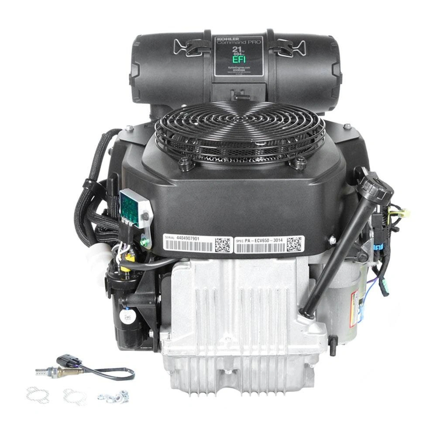
Contents Section 1. Safety and General Information ................Section 2. Tools & Aids ......................Section 3. Troubleshooting ...................... Section 4. Air Cleaner and Air Intake System ................. Section 5. Electronic Fuel Injection (EFI) System ..............Section 6. Lubrication System ....................Section 7.
Section 1 Safety and General Information Section 1 Safety and General Information Safety Precautions To ensure safe operation, please read the following statements and understand their meaning. Also refer to your equipment manufacturer's manual for other important safety information. This manual contains safety precautions which are explained below.
Page 6
Section 1 Safety and General Information WARNING WARNING Carbon Monoxide can cause severe Explosive Fuel can cause fi res and nausea, fainting or death. severe burns. Avoid inhaling exhaust fumes, and Fuel systems ALWAYS remains under never run the engine in a closed HIGH PRESSURE.
Page 7
50 hours using standard the viscosity based on the air temperature at the time petroleum based oil before switching to of operation as shown in the following table. synthetic oil. Kohler 10W-30 10W-30 SAE 30 5W-30 °F -20...
Page 8
Gasoline/Alcohol Blends Gasohol (up to 10% ethyl alcohol, 90% unleaded gasoline by volume) is approved as a fuel for Kohler engines. Other gasoline/alcohol blends including E20 Figure 1-3. Oil Container Logo. and E85 are not to be used and not approved. Any...
Page 9
• Have starter serviced. Section 7 Every 500 Hours ¹Perform these maintenance procedures more frequently under extremely dusty, dirty conditions. ²Have a Kohler Engine Service Dealer perform this service. Low-profi le air cleaner. Heavy-duty air cleaner. Storage Run the engine for 2 to 3 minutes to get stabilized If the engine will be out of service for two months or fuel into the rest of the system.
Page 10
Section 1 Safety and General Information Dimensions in millimeters. Inch equivalents shown in [ ]. Figure 1-4. Typical Engine Dimensions - ECV749 with Heavy-Duty Air Cleaner.
Page 11
Section 1 Safety and General Information 427.72 [16.839] 302.03 60.00 [11.891] Dimensions in millimeters. [2.362] AIR CLEANER Inch equivalents shown in [ ]. COVER REMOVAL 12.15 [.478] 16.31 17.01 [.670] [.642] SPARK SPARK PLUG PLUG FUEL FILTER 397.06 [15.632] 334.62 [13.174] 2X 89.41 [3.520]...
Page 12
Section 1 Safety and General Information General Specifi cations Power (@3600 RPM, exceeds Society of Automotive Engineers-Small Engine Test Code J1940.) ECV630 ............................14.1 kW (19 HP) ECV650 ............................15.7 kW (21 HP) ECV680 ............................17.2 kW (23 HP) ECV730 ............................18.6 kW (25 HP) ECV740 ............................
Page 13
Section 1 Safety and General Information Running Clearance .....................0.025/0.105 mm (0.001/0.004 in.) Bore I.D. New ........................20.000/20.025 mm (0.7874/0.7884 in.) Max. Wear Limit ....................20.038 mm (0.7889 in.) Camshaft Bearing Surface O.D. New ........................19.920/19.975 mm (0.7843/0.7864 in.) Max. Wear Limit ....................19.914 mm (0.7840 in.) Connecting Rod Cap Fastener Torque (torque in increments) ............11.6 N·m (103 in.
Page 14
Section 1 Safety and General Information Crankshaft - Flywheel End Main Bearing Journal O.D. - New ......................40.913/40.935 mm (1.6107/1.6116 in.) O.D. - Max. Wear Limit ..................40.843 mm (1.608 in.) Max. Taper Limit ....................0.022 mm (0.0009 in.) Max. Out-of-Round Limit ..................0.025 mm (0.0010 in.) Crankshaft - Oil Pan End Main Bearing Journal O.D.
Page 15
Section 1 Safety and General Information Governor Governor Cross Shaft -to-Crankcase Running Clearance ........0.025/0.126 mm (0.0009/0.0049 in.) Governor Cross Shaft O.D. New ........................7.949/8.000 mm (0.3129/0.3149 in.) Max. Wear Limit ....................7.936 mm (0.3124 in.) Governor Gear Shaft -to-Governor Gear Running Clearance ..................0.090/0.160 mm (0.0035/0.0063 in.) Governor Gear Shaft O.D.
Page 16
Section 1 Safety and General Information Oil Cooler Oil Cooler/Adapter Nipple Torque .................28.5 N·m (21 ft . lb.) Oil Cooler Fastener Torque Top Fastener ......................2.8 N·m (25 in. lb.) Bott om Fastener ....................2.3 N·m (20 in. lb.) Piston, Piston Rings, and Piston Pin Piston-to-Piston Pin Running Clearance ..............0.006/0.017 mm (0.0002/0.0007 in.) Piston Pin Bore I.D.
Page 17
Section 1 Safety and General Information Solenoid (Starter) Mounting Hardware Torque ..................4.0-6.0 N·m (35-53 in. lb.) Nut, Positive (+) Brush Lead Torque ...............8.0-11.0 N·m (71-97 in. lb.) Stator Mounting Screw Torque ....................6.2 N·m (55 in. lb.) into new holes 4.0 N·m (35 in. lb.) into used holes Valve Cover Valve Cover Fastener Torque..................6.2 N·m (55 in.
Page 18
Section 1 Safety and General Information General Torque Values Metric Fastener Torque Recommendations for Standard Applications Tightening Torque: N·m (in. lb.) + or - 10% Property Class Noncritical Fasteners Into Aluminum Size 1.2 (11) 1.7 (15) 2.9 (26) 4.1 (36) 5.0 (44) 2.0 (18) 2.5 (22)
Page 19
Section 1 Safety and General Information English Fastener Torque Recommendations for Standard Applications Tightening Torque: N·m (in. lb.) + or - 20% Bolts, Screws, Nuts and Fasteners Grade 2 or 5 Assembled Into Cast Iron or Steel Fasteners Into Aluminum Grade 2 Grade 5 Grade 8...
Page 20
Section 1 Safety and General Information 1.16...
SE Tools KLR-82417 To protect seal during camshaft installation. Cylinder Leakdown Tester Kohler 25 761 05-S For checking combustion retention and if cylinder, piston, rings, or valves are worn. Electronic Fuel Injection (EFI) Diagnostic Soft ware Kohler 25 761 23-S Use with Laptop or Desktop PC.
Page 22
Tools & Aids Tools (Continued) Description Source/Part No. Hydraulic Valve Lift er Tool Kohler 25 761 38-S To remove and install hydraulic lift ers. Ignition System Tester Kohler 25 455 01-S For testing output on all systems, including CD. Off set Wrench (K & M Series) Kohler 52 455 04-S To remove and reinstall cylinder barrel retaining nuts.
Page 24
1 in. O.D. tooth segment of the ring gear as shown. (Kohler Part No. 12 468 05-S). Assemble the cap- screw and washer to the joint surface of the rod, 2. Grind off any burrs or sharp edges.
Page 25
Section 3 Troubleshooting Section 3 Troubleshooting Troubleshooting Guide 3. Clogged fuel line or fuel fi lter. 4. Loose or faulty wires or connections. When troubles occur, be sure to check the simple 5. Faulty spark plugs. causes which, at fi rst, may seem too obvious to be 6.
Page 26
Section 3 Troubleshooting Engine Overheats external surfaces. Dirt or debris on these areas 1. Air intake/grass screen, cooling fi ns, oil cooler or are causes of higher operating temperatures and cooling shrouds clogged. overheating. 2. Excessive engine load. • 3.
Page 27
Section 3 Troubleshooting Basic Engine Tests 4. Close the shut-off clamp before stopping the engine. Crankcase Vacuum Test To test the crankcase vacuum with the Vacuum/ A partial vacuum should be present in the Pressure Gauge Kit: crankcase when the engine is operating. Pressure in the crankcase (normally caused by a clogged or 1.
Page 28
Section 3 Troubleshooting Compression Test If the fl ywheel end is more accessible, use a A compression test can be performed using a breaker bar and socket on the fl ywheel nut/ compression tester. Follow the manufacturers screw to hold it in position. An assistant may be instructions for performing the test.
Section 4 Air Cleaner and Air Intake System Section 4 Air Cleaner and Air Intake System This engine is equipped with a heavy-duty air cleaner, low-profi le air cleaner, or special air cleaner supplied by the equipment manufacturer. Heavy-Duty Air Cleaner General These engines use a heavy-duty style air cleaner shown in Figure 4-1, consisting of a cylindrical housing mounted to a bracket, on the thrott le body/intake manifold.
Page 30
Nuts the elements. Replace dirty, bent or damaged elements with new genuine Kohler elements as required. Handle the new elements carefully; do not use if the sealing surfaces are bent or Figure 4-5. Air Cleaner Hex Flange Nuts.
Page 31
Section 4 Air Cleaner and Air Intake System Service Element Check the air cleaner daily or before starting the engine. Check for and correct any buildup of dirt and debris, along with loose or damaged components. NOTE: Operating the engine with loose or damaged air cleaner components could allow unfi...
Page 32
5. Reset the governor (see Section 5). Replace a dirty, bent, or damaged element with a genuine Kohler element. Handle new elements Air Intake/Cooling System carefully; do not use if the sealing surfaces are To ensure proper cooling, make sure the fi...
Page 33
Section 5 EFI Fuel System Section 5 Electronic Fuel Injection (EFI) System Contents Page(s) Description Fuel Pump Module Connector Removal ......................... 5.2 Initial Starting/Priming Procedure ........................... 5.2 Fuel Recommendations .............................. 5.2 EFI Fuel System Components ..........................5.2-5.3 Operation..................................5.3 Important Service Notes ............................5.3-5.4 Electrical Components Electronic Control Unit (ECU) ..........................
Fuel Pump Module Fuel Connector Removal Gasohol (up to 10% ethyl alcohol, 90% unleaded instructions below. gasoline by volume) is approved as a fuel for Kohler engines. Other gasoline/alcohol blends including E20 Fuel Pump Module Fuel Connector and E85 are not to be used and not approved. Any...
Section 5 EFI Fuel System • Fuel Line(s) system operates closed loop when all three of the • Fuel Injectors following conditions are met: • Thrott le Body/Intake Manifold • Electronic Control Unit (ECU) a. The oil temperature is greater than 60°C (140°F). •...
Page 36
Section 5 EFI Fuel System • Avoid direct water or spray contact with system General components. The ECU is the brain or central processing computer of the entire EFI system. During operation, sensors • Do not disconnect or reconnect the ECU wiring continuously gather data which is relayed through harness connector or any individual components the wiring harness to input circuits within the...
Page 37
Section 5 EFI Fuel System The relationship between the ECU and the thrott le Electrical System position sensor (TPS) is very critical to proper The EFI system is a 12 VDC negative ground system, system operation. If the TPS or ECU is changed, designed to operate down to a minimum of 6.0 or the mounting position of the TPS is altered, the volts.
Page 38
Section 5 EFI Fuel System Black Connector Grey Connector Pin # Function Pin # Description Ignition Coil #1 Ground Not Used Batt ery Ground Not Used Diagnostic Communication Line Malfunction Indicator Light (MIL) Ground Speed Sensor input Not Used Fuel Injector Output #1 Ground Not Used Fuel Injector Output #2 Ground Not Used...
Page 39
DARK GREEN 6-Terminal DARK BLUE Connector Rectifier- Regulator Pressure Fuel Pump Starter Battery Switch Motor Stator BLACK A B C A B C Fuel Fuel Ignition Ignition Crankshaft Oxygen Throttle Manifold Intake Diagnostic Injector Injector Coil Coil Position Sensor Position Absolute Temperature Connector...
Page 40
Section 5 EFI Fuel System Crankshaft Position Sensor 4. Disconnect the Black connector from the ECU. 5. Connect an ohmmeter between the #4 and #13 pin terminals. A resistance value of 325-395 at room temperature (20°C, 68°F) should be obtained. If resistance is correct, check the mounting, air gap, fl...
Page 41
Section 5 EFI Fuel System Mounted on the thrott le body and operated directly 4. Leave the leads connected to the pin terminals as off the end of the thrott le shaft , the TPS works as a described in step 3. Rotate the thrott le shaft potentiometer, varying the voltage signal to the ECU slowly to the full thrott le position.
Page 42
Engine (Oil) Temperature Sensor ECU Reset Procedure 1. Turn key OFF. 2. Install Red wire jumper (Figure 5-6) from Kohler EFI service kit on to service port (connect the white wire to the black wire in the 4 way diagnostic port).
Page 43
Section 5 EFI Fuel System 3. Unplug the Black connector from the ECU. The purpose of an air temperature sensor is to help the ECU calculate air density. The higher the air 4. With the sensor still connected, check the temperature gets the less dense the air becomes.
Page 44
Section 5 EFI Fuel System Oxygen Sensor Service The temperature must be controlled very accurately and gas constituents measured to a high degree of accuracy for absolute sensor measurements. Since this requires laboratory equipment, it is not possible to distinguish a marginally in specifi cation sensor from a marginally out of specifi...
Page 45
Section 5 EFI Fuel System Visual Inspection NOTE: Using the diagnostic soft ware, the wiring and 1. Look for a damaged or disconnected sensor-to- ECU integrity can be checked by grounding engine harness connection. the signal wire; the output of the sensor, read on the soft ware, should be around 4 mv.
Page 46
Section 5 EFI Fuel System Oxygen Sensor Symptoms and Corrections CONDITION POSSIBLE CAUSE CORRECTION Low voltage output Shorted sensor or sensor circuit Replace sensor or repair wiring Shorted lead wire Wiring shorted to ground Remove source of external Contamination of air reference contamination, protect air reference area Use recommended torque at...
Section 5 EFI Fuel System Manifold Absolute Pressure Sensor 3. Check to make sure the intake manifold is not loose and the MAP sensor is not loose. Loose parts would allow a vacuum leak, making the MAP sensor report misleading information to the Locking ECU.
Page 48
Section 5 EFI Fuel System The injectors have sequential fueling that open and NOTE: Do not apply voltage to the fuel injector(s). close once every other crankshaft revolution. The Excessive voltage will burn out the amount of fuel injected is controlled by the ECU injector(s).
Page 49
Section 5 EFI Fuel System Injector leakage is very unlikely, but in those rare 11. Disconnect the breather tube on top of the thrott le instances it can be internal (past the tip of the valve body. needle), or external (weeping around the injector O-rings).
Section 5 EFI Fuel System 23. Reverse the appropriate procedures to install the General new injector(s) and reassemble the engine. Use A high-voltage, solid-state, batt ery ignition system new O-rings and retaining clips any time an is used with the EFI system. The ECU controls the injector is removed (new replacement injectors ignition output and timing through transistorized include new O-rings and retaining clips).
Section 5 EFI Fuel System 2) Connect an ohmmeter set on the Rx1 scale Fuel Components to the primary terminals of the coil. Primary resistance should be 0.5-0.8 . Fuel Pump 3) Connect an ohmmeter set on the Rx10K General scale between the spark plug boot terminal An electric fuel pump module and a lift pump (two and the B+ primary terminal.
Page 52
Disconnect the fuel coupler from the fuel pump module and insert the pressure test jumper (from Kohler EFI Service Kit) between the high pressure fuel line and the fuel pump module.
Periodically inspect the fi lter and replace every 200 harness. operating hours or more frequently under extremely dusty or dirty conditions. Use only a genuine Kohler 7. If voltage at the plug was good, and there was fi lter and install it according to the directional arrows.
Section 5 EFI Fuel System Service Throttle Body/Intake Manifold Assembly The high pressure fuel line is mounted to the intake manifold. No specifi c servicing is required unless operating conditions indicate that it needs replacement. It can be detached by removing the two mounting screws, wire ties, and the injector retaining clips.
Section 5 EFI Fuel System General If the governor/thrott le components are all intact, The idle speed is the only adjustment that may be but you think there may be a problem with the performed on the EFI system. The standard idle adjustment, follow Procedure A to check the sett ing.
Page 56
Section 5 EFI Fuel System 3. Rotate the governor lever and shaft 3. Insert a nail or Allen wrench into the hole in the counterclockwise until it stops. Use only enough top of the cross shaft . Using light pressure, rotate pressure to hold it in that position.
Section 5 EFI Fuel System Troubleshooting Engine misses, hesitates, or stalls under load 1. Fuel injector(s), fuel fi lter, fuel line, or fuel pick-up dirty/restricted General 2. Dirty air cleaner When troubleshooting a problem on an engine 3. Insuffi cient fuel pressure or fuel delivery with EFI, basic engine operating problems must 4.
Section 5 EFI Fuel System 3. Remove the spark plugs and check for fuel at the 4. The MIL will blink a series of times. The number tips. of times the MIL blinks represents a number in the blink code. a.
Page 59
Section 5 EFI Fuel System Example of Diagnostic Display One second pause Fault One second pause Code 0107 One second pause Three second pause One second pause Code 61 This is a 0107 fault code with the 61 message end code. Figure 5-29.
Page 60
Section 5 EFI Fuel System Diagnostic Code Summary Fault Code Connection or Failure Description 0031 Oxygen Sensor Heater Circuit High Voltage 0032 Oxygen Sensor Heater Circuit Low Voltage 0107 Manifold Absolute Pressure Sensor Circuit Low Voltage or Open 0108 Manifold Absolute Pressure Sensor Circuit High Voltage 0112 Intake Air Temperature Sensor Circuit Low Voltage 0113...
Page 61
Section 5 EFI Fuel System Code: 0031 Code: 0108 Component: Oxygen Sensor Heater Component: Manifold Absolute Pressure Sensor Fault: O2S Heater Circuit High Voltage Fault: MAP Circuit High Voltage Condition: System voltage too high, shorted Condition: Intake manifold leak, shorted connection connection or faulty sensor.
Page 62
Section 5 EFI Fuel System 3. ECU Black pin 16 to TPS pin 2. Code: 0117 Component: Coolant/Oil Sensor 3. Thrott le Body Related a. Thrott le shaft inside TPS worn, broken, or Fault: Coolant/Oil Temperature Sensor damaged. Circuit Low Voltage b.
Page 63
Section 5 EFI Fuel System 2. TPS Learn Procedure Incorrect 4. Systems Related a. Lean condition (check oxygen sensor signal a. Ignition (spark plug, plug wire, ignition coil). with VOA and see Oxygen Sensor section). b. Fuel (fuel type/quality, injector, fuel pressure too low, fuel pump module or lift pump).
Page 64
Section 5 EFI Fuel System Code: 0174 Code: 0202 Component: Fuel System Component: Fuel Injector Fault: Lean fuel condition Fault: Injector 2 Circuit Malfunction Condition: Fuel inlet screen/fi lter plugged, low Condition: Injector damaged or faulty, shorted or open pressure at high pressure fuel line, TPS malfunction, connection.
Page 65
Section 5 EFI Fuel System Code: 0336 Code: 0351 Component: Crankshaft Position Sensor Component: Ignition Coil Fault: Crankshaft Position Sensor Noisy Fault: Cylinder 1 Ignition Coil Malfunction Signal Condition: Broken wire in harness (may not be Condition: Air gap incorrect, loose sensor, faulty/bad visible), shorted connection or faulty sensor.
Section 5 EFI Fuel System Troubleshooting Flow Chart Code: 0563 The following fl ow chart provides an alternative Component: System Voltage method of troubleshooting the EFI system. The chart will enable you to review the entire system in about Fault: System Voltage High 10-15 minutes.
Page 67
Section 5 EFI Fuel System EFI Diagnostic Flow Diagram START OF TEST PROCEED TO START OF TEST FOR RETEST KEY ON MALFUNCTION REFER TO DIAGNOSTIC AID #1 INDICATOR LIGHT SYSTEM POWER REFER TO DIAGNOSTIC AID #2 ARE FAULT CODES FAULT CODES PRESENT? CLEAR CODES REFER TO DIAGNOSTIC AID #3...
Code 0352 - Cylinder 2 Ignition Coil Malfunction supply to bulb will be part of vehicle wire Code 0562 - System Voltage Low harness. Kohler key switch model will have Code 0563 - System Voltage High MIL on engine with 12V supply to bulb.
Page 69
Section 5 EFI Fuel System 6. ECU 7. Vehicle safety interlocks, ground signal on safety wire. Diagnostic Aid #7 FUEL SYSTEM ELECTRICAL (no fuel delivery) Possible causes: 1. No fuel 2. Air in high pressure fuel line 3. Fuel valve shut OFF 4.
Figure 6-2. Oil Container Logo. Kohler 10W-30 The top position of the symbol shows service class such as API SERVICE CLASS SJ. The symbol may...
Page 72
Section 6 Lubrication System Check Oil Level 5. If the level is low, add oil of the proper type (Refer to Oil Recommendations on page 6.1) and The importance of checking and maintaining to the correct level. Always check the level before the proper oil level in the crankcase cannot be adding more oil.
Page 73
Replace the oil fi lter at least every other oil change (every 200 hours of operation). Always use a genuine Kohler oil fi lter. Replace the oil fi lter as follows: 1. Drain the oil from the engine crankcase. Remove one of the oil drain plugs and the oil fi...
Page 74
Section 6 Lubrication System ™ Oil Sentry To install the switch, follow these steps: 1. If no sealant is preapplied, apply pipe sealant with Tefl on (Loctite ® ™ ® Thread Sealant General ® or equivalent) to the threads of the switch. Some engines are equipped with an optional Oil Sentry™...
® RC12YC (Kohler Part No. 12 132 02-S). ® RFI compliant engines use a Champion XC12YC (Kohler 25 132 14-S) spark plug. A ® high-performance spark plug, Champion Platinum 3071 is also available. Equivalent alternate brand plugs can also be used.
Page 76
Section 7 Electrical System and Components Normal: A plug taken from an engine operating under Wet Fouled: A wet plug is caused by excess fuel or normal conditions will have light tan or grey colored oil in the combustion chamber. Excess fuel could be deposits.
Page 77
Section 7 Electrical System and Components 2. Keep the cables, terminals, and external surfaces Battery of the batt ery clean. A build-up of corrosive acid or grime on the external surfaces can cause the General batt ery to self-discharge. Self-discharge occurs A 12-volt batt ery with 400 cold cranking amps is rapidly when moisture is present.
Section 7 Electrical System and Components Stator Battery Charging System The stator is mounted on the crankcase behind the fl ywheel. Follow the procedures in Section 8 - General Disassembly and Section 10 - Reassembly if stator These engines are equipped with a 20 or 25 amp replacement is necessary.
Page 79
Section 7 Electrical System and Components Rectifi er-Regulator The rectifi er-regulator is mounted on the blower Ground housing. See Figure 7-5. To replace it, disconnect the Lead connector, remove the two mounting screws, and metal grounding strap. Lead NOTE: When installing the rectifi er-regulator, take note of the terminal markings and install the connector accordingly.
Page 80
Section 7 Electrical System and Components Troubleshooting Guide 20/25 Amp Battery Charging Systems When problems occur in keeping the batt ery charged or the batt ery charges at too high a rate, the problem can usually be found somewhere in the charging system or with the batt ery. NOTE: Always zero ohmmeter on each scale before testing to ensure accurate readings.
Page 81
Section 7 Electrical System and Components Battery 1. Perform same test as step 1. If the voltage is 14.7 volts or less the charging system is OK. Continuously 1 above. The batt ery is unable to hold a charge. Service batt ery or Charges at replace as necessary.
Page 82
Section 7 Electrical System and Components Troubleshooting Guide - Starting Diffi culties Problem Possible Fault Correction 1. Check the specifi c gravity of batt ery. If low, recharge or replace Battery batt ery as necessary. 1. Clean corroded connections and tighten loose connections. 2.
Page 83
Section 7 Electrical System and Components Starter Disassembly 1. Remove the hex nut and disconnect the positive (+) brush lead/bracket from the solenoid terminal. 2. Remove the three screws securing the solenoid to the starter. See Figure 7-10. Torx Head Screws Figure 7-12.
Page 84
Section 7 Electrical System and Components 6. Remove the rubber grommet and backing plate from the end cap. See Figure 7-15. Figure 7-17. Retaining Ring Detail. 10. Remove the retainer from the armature shaft . Save the stop collar. Figure 7-15. Rubber Grommet and Bushing Plate. NOTE: Do not reuse the old retainer.
Page 85
Section 7 Electrical System and Components Inspection Commutator O.D. Drive Pinion Check and inspect the following areas: a. The pinion teeth for abnormal wear or damage. b. The surface between the pinion and the clutch mechanism for nicks, or irregularities which could cause seal damage.
Page 86
Starter Service The brushes and springs are serviced as a set (4). Clean the drive lever and armature shaft . Apply Use Kohler Brush and Spring Kit, if replacement is Kohler electric starter drive lubricant (see Section 2) necessary. (Versilube G322L or Mobil Temp SHC 32) to the lever and shaft .
Page 87
Section 7 Electrical System and Components 3. Install the off set thrust (stop) washer so the 7. Install the backing plate, followed by the rubber smaller off set of the washer faces the retainer/ grommet, into the matching recess of the drive collar.
Page 88
Section 7 Electrical System and Components Figure 7-29. Installing Thrust Washer. Figure 7-31. Removing Retaining Clips. 10. Starter reassembly when replacing the Brushes/ b. Position each of the brushes back in their slots Brush Holder Assembly: so they are fl ush with the I.D. of the brush holder assembly.
Page 89
Section 7 Electrical System and Components Figure 7-33. Installing Brush Holder Assembly Figure 7-35. Torquing Brush Holder Screws. using Tool with Extension. 13. Hook the plunger behind the upper end of 11. Install the end cap onto the armature and frame, the drive lever, and install the spring into the aligning the thin raised rib in the end cap with solenoid.
Page 90
Section 7 Electrical System and Components Solenoid Test Procedure 12 volt Test Leads Momentary Solenoid Shift Style Starters Connection Only Disconnect all leads from the solenoid including the positive brush lead att ached to the lower stud VOM Leads terminal. Remove the mounting hardware and separate the solenoid from the starter for testing.
Page 91
Section 7 Electrical System and Components Test 4. Solenoid Hold-In Coil/Contact Continuity. Use an ohmmeter set to the audible or Rx2K scale, and connect the two ohmmeter leads to the two large post terminals. Perform the preceding test (3) and check for continuity.
Page 92
Section 7 Electrical System and Components 7.18...
Page 93
Section 8 Disassembly Section 8 Disassembly 13. Remove oil separator and hardware. WARNING 14. Remove grass screen. 15. Remove outer baffl es and blower housing. Accidental Starts can cause severe 16. Remove Oil Sentry™. injury or death. 17. Remove inner baffl es and breather cover. Disconnect and ground spark plug 18.
Page 94
Section 8 Disassembly Drain Oil From Crankcase and Remove Oil 4. Remove and discard the oil fi lter. See Figure 8-4. Filter Remove Oil Cooler 1. Remove oil fi ll cap/dipstick and one of the oil The oil cooler can now be removed from the engine. drain plugs.
Page 95
Section 8 Disassembly 2. Remove the two upper screws securing the air Remove Top Mount Control Panel cleaner to the mounting bracket and remove the 1. Remove the thrott le control shaft nut on top of air cleaner assembly. See Figure 8-6. the thrott le shaft and remove the thrott le control lever and spring.
Page 96
Section 8 Disassembly Remove External Governor Controls Remove Lift Fuel Pump and Fuel Pump 1. Disconnect the governor spring att ached to the Module governor lever. See Figure 8-11. Note the hole location for reassembly. WARNING 2. Disconnect the thrott le linkage spring, remove Explosive Fuel can cause fi...
Page 97
Section 8 Disassembly Fuel Pump Module 6. Using a side cutt er or similar tool, cut the Oetiker 1. Remove the three screws securing the fuel pump Clamp off to remove the inlet fuel line. A new module. Oetiker Clamp will need to be used for reinstall. See Figure 8-16.
Page 98
Section 8 Disassembly 5. If equipped, remove the two screws securing the heavy-duty air cleaner bracket, take off the bracket and slide the thrott le body off the intake manifold. See Figure 8-21. Figure 8-18. Disconnect Breather Tube. 3. Disconnect the thrott le position sensor connector. See Figure 8-19.
Page 99
Section 8 Disassembly Figure 8-23. Disconnect ECU Electrical Figure 8-25. Remove Oil Separator Assembly. Connectors. Remove Grass Screen Remove Electric Starter Motor and 1. Remove the four socket head cap screws securing the metal grass screen and remove the screen. See Electronic Control Unit Bracket Figure 8-26 1.
Page 100
Section 8 Disassembly 2. Remove the silver plated rectifi er-regulator Remove Four Screws ground strap screw fastened to the crankcase. The rectifi er-regulator does not have to be detached from the blower housing. 3. Disconnect the three fuse connectors att ached to the outer baffl...
Page 101
Section 8 Disassembly Figure 8-31. Removing Blower Housing. Figure 8-33. Removing Inner Baffl es. 3. Disconnect and remove the oil temperature Remove Oil Sentry™ sensor. See Figure 8-34. 1. Disconnect the lead from the Oil Sentry™ switch. NOTE: This is optional. Removing the oil 2.
Page 102
Section 8 Disassembly 5. Pry under the protruding edge of the breather cover with a screwdriver to break the gasket seal. See Figure 8-35. Do not pry on the sealing surfaces as it could cause damage resulting in leaks. 6. Remove the breather cover and gasket. See Figure 8-36.
Page 103
Section 8 Disassembly 2. Detach the connector. 3. Remove the hex fl ange screw and pull the MAP sensor out of the intake manifold. See Figure 8-41. Figure 8-43. Remove Fuel injector. 3. When removed, pull off the metal retaining clip connecting the fuel injector to the fuel injector cap.
Page 104
Section 8 Disassembly 4. Remove the intake manifold and the intake manifold gaskets. See Figure 8-48. Figure 8-45. Remove Screw for Ground Terminal. 2. Remove the four hex fl ange screws securing the intake manifold to the cylinder heads. Note Figure 8-48.
Page 105
Section 8 Disassembly Hydraulic Lifter Tool Figure 8-52. Removing Hydraulic Lifters. Figure 8-50. Removing Cylinder Head Fasteners. 2. Mark the location of the push rods as either intake or exhaust and cylinder 1 or 2. Push rods should always be reinstalled in the same positions.
Page 106
Section 8 Disassembly Valve Seal Figure 8-55. Removing Valves with Valve Spring Figure 8-57. Valve Seal Location. Compressor. Remove Fan and Flywheel 3. Once the valve spring is compressed, remove the 1. Remove the four shoulder bolts securing the fan valve spring keepers, then remove the following if still att ached and remove fan.
Page 107
Section 8 Disassembly NOTE: Always use a fl ywheel puller to remove the fl ywheel from the crankshaft . Do not strike the crankshaft or fl ywheel, as these parts could become cracked or damaged. Striking the puller or crankshaft can cause the crank gear to move, aff...
Page 108
Section 8 Disassembly Remove Camshaft 1. Remove the camshaft and shim (if used). See Figure 8-63. Shim Figure 8-65. Removing Governor Cross Shaft. Remove Connecting Rods with Pistons and Rings Figure 8-63. Removing Camshaft. 1. Remove the two hex fl ange screws securing the closest connecting rod end cap.
Page 109
Section 8 Disassembly Figure 8-67. Removing Connecting Rod and Piston Figure 8-69. Removing Crankshaft. Assembly. Remove Flywheel End Oil Seal 3. Repeat the above procedure for the other 1. Remove the oil seal from the crankcase. See connecting rod and piston assembly. Figure 8-70.
Section 9 Inspection and Reconditioning Section 9 Inspection and Reconditioning This section covers the operation, inspection, and camshaft will be necessary if any of these conditions repair/reconditioning of major internal engine exist. components. The following components are not covered in this section. They are covered in sections of Crankshaft their own: Inspection and Service...
Page 112
Section 9 Inspection and Reconditioning Procedure to Install New Plug: High Point from 1. Use a single cylinder camshaft pin Part No. Fillet Intersections 47 380 09-S as a driver and tap the plug into the plug bore until it seats at the bott om of the bore. The Fillet Must Make sure the plug is tapped in evenly to prevent Blend Smoothly...
Page 113
Section 9 Inspection and Reconditioning NOTE: Kohler pistons are custom-machined to The fi nal cleaning operation should always be a exacting tolerances. When oversizing a thorough scrubbing with a brush and hot, soapy cylinder, it should be machined exactly water. Use a strong detergent that is capable of 0.25 mm (0.010 in.) or 0.50 mm (0.020 in.)
Page 114
Replace the fl ywheel, the crankshaft , and the key if the fl ywheel key is sheared or the keyway is damaged. Inspect the ring gear for cracks or damage. Kohler does not provide ring gears as a serviceable part.
Page 115
Section 9 Inspection and Reconditioning Hard starting, or loss of power accompanied by high fuel consumption may be symptoms of faulty valves. Although these symptoms could also be att ributed to worn rings, remove and check the valves fi rst. Aft er removal, clean the valve heads, faces, and stems with a power wire brush.
Page 116
Section 9 Inspection and Reconditioning Excessive Combustion Temperatures: The white Stem Corrosion: Moisture in fuel or from deposits seen here indicate very high combustion condensation are the most common causes of valve temperatures, usually due to a lean fuel mixture. stem corrosion.
Page 117
Section 9 Inspection and Reconditioning Valve Guides If a valve guide is worn beyond specifi cations, it will not guide the valve in a straight line. This may result in burnt valve faces or seats, loss of compression, and Valve Seat excessive oil consumption.
Page 118
Section 9 Inspection and Reconditioning Ring failure is usually indicated by excessive oil Detonation damage occurs when a portion of the fuel consumption and blue exhaust smoke. When rings charge ignites spontaneously from heat and pressure fail, oil is allowed to enter the combustion chamber shortly aft er ignition.
Page 119
Section 9 Inspection and Reconditioning Replacement pistons are available in STD bore size, and 0.25 mm (0.010 in.), and 0.50 mm (0.020 in.) oversize. Replacement pistons include new piston ring sets and new piston pins. Replacement ring sets are also available separately for STD, 0.25 mm (0.010 in.), and 0.50 mm (0.020 in.) oversize pistons.
Page 120
Check the base surface of the hydraulic lift ers for wear Piston or damage. If the lift ers need to be replaced, apply a liberal coating of Kohler lubricant (see Section 2) to the base of each new lift er before it is installed. Compression “Bleeding”...
Section 9 Inspection and Reconditioning Disassembly Reassembly The governor gear must be replaced once it is 1. Install the locking tab thrust washer on the removed from the oil pan. governor gear shaft with the tab down. NOTE: The governor gear is held onto the shaft by 2.
Page 122
Section 9 Inspection and Reconditioning 4. Aft er torquing, rotate the gear and check for freedom of movement. Make sure there is no binding. If binding occurs, loosen the screws, reposition the pump, retorque the hex fl ange screws and recheck the movement. Crankcase Breather System The breather system is designed to control the amount of oil in the head area and still maintain the necessary...
Page 123
Section 9 Inspection and Reconditioning Figure 9-18. Oil Separator. Governor Cross Shaft Oil Seal If the governor cross shaft seal is damaged and/or leaks, replace it using the following procedure. Remove the oil seal from the crankcase and replace it with a new one. Install the new seal to the depth shown in Figure 9-19 using a seal installer.
Page 124
Section 9 Inspection and Reconditioning 9.14...
Page 125
Section 10 Reassembly Section 10 Reassembly General 18. Install oil temperature sensor. 19. Install Oil Sentry NOTE: Make sure the engine is assembled using 20. Install blower housing and outer baffl es. all specifi ed torque values, tightening 21. Install grass screen. sequences, and clearances.
Page 126
Section 10 Reassembly 4.5 mm (.177 in.) Oil Seal Cylinder #2 Cylinder #1 Figure 10-2. Installing Oil Seal in Crankcase. Figure 10-4. Proper Piston Connecting Rod Orientation. Install Crankshaft 1. Stagger the piston rings in the grooves until the 1. Lubricate the crankshaft journals and connecting end gaps are 120°...
Page 127
Section 10 Reassembly NOTE: Align the chamfer of the connecting rod with the chamfer of its mating end cap. When installed, the fl at faces of the connecting rods should face each other. The faces with the raised rib should be toward the outside.
Page 128
Section 10 Reassembly Governor Cross Shaft Oil Seal Timing Marks Figure 10-10. Aligning Crankshaft and Camshaft Figure 10-12. Oil Seal Depth in Oil Pan. Timing Marks. Install Oil Pan Assembly Oil Pump Assembly Most engines use an oil pan gasket. Optionally, RTV The oil pump is mounted inside the oil pan.
Page 129
Section 10 Reassembly Apply 1.5 mm (1/16 in.) bead of sealant. RTV must be all around O-ring groove Point B Figure 10-15. Torquing Oil Pan Fasteners. Point A Install Stator and Backing Plate 1. Apply pipe sealant with Tefl on ®...
Page 130
Section 10 Reassembly Figure 10-17. Route Stator Leads in Groove. Figure 10-19. Clean and Dry Taper of Crankshaft. Figure 10-18. Installing Backing Plate. Figure 10-20. Clean and Dry Flywheel Hub. 1. Install the woodruff key into the keyway of the Install Flywheel and Fan crankshaft .
Page 131
Section 10 Reassembly Figure 10-21. Carefully Align Keyway to Key. Figure 10-23. Installing Fan. 3. Install the hex fl ange screw and washer. Install Cylinder Heads and Hydraulic Lifters 4. Use a fl ywheel strap wrench or holding tool to 1.
Page 132
Section 10 Reassembly Figure 10-25. Installing Hydraulic Lifters. Figure 10-27. Installed Breather Reed. NOTE: Hydraulic lift ers should always be Valve Stem Seals installed in the same position as before These engines use valve stem seals on the intake disassembly. The exhaust lift ers are valves and on the exhaust valves.
Page 133
Section 10 Reassembly b. Thread the opposite end of the stud, with the preapplied locking compound, into the Valve Keepers crankcase, until the specifi ed height from the crankcase surface is achieved. See Figure 10-31. When threading in the studs, use a steady tightening motion without interruption until the proper height is obtained.
Page 134
Section 10 Reassembly Figure 10-32. Torquing the Cylinder Head Figure 10-34. Cylinder Head Fastener Torque Mounting Nuts (Stud Design). Sequence. Heads secured with hex fl ange screws: Install Push Rods and Rocker Arms 2. Install a new cylinder head gasket (part number NOTE: Push rods should always be installed in the facing up).
Page 135
Section 10 Reassembly 3. Install new plugs and torque to 24.4-29.8 N·m (18-22 ft . lb.). See Figure 10-38. Figure 10-36. Torquing Rocker Arm Screws. 4. Use a spanner wrench or rocker arm lift ing tool (see Section 2), to lift the rocker arms and position Figure 10-38.
Page 136
Section 10 Reassembly 4. Place wire harness conduit in clip and snap clip together. Figure 10-40. Installing Intake Manifold with Wiring Harness. Figure 10-43. Install Wire Harness Clip. Install Fuel Injectors NOTE: Ensure all parts are clean, undamaged and free of debris and make sure the electrical connectors have the seal in place.
Page 137
Section 10 Reassembly 5. Install the fuel injector cap hex fl ange screw into Install Crankshaft Position Sensor the intake manifold and torque to 7.3 N·m NOTE: Ensure all parts are clean, undamaged and (65. in. lb.). See Figure 10-45. free of debris and make sure the electrical connectors have the seal in place.
Page 138
Section 10 Reassembly Figure 10-48. Valve Cover Fastener Torque Figure 10-50. Installing Screws (Locations 3 and Sequence. 4. Install the inner baffl es using the remaining two Install Breather Cover and Inner Baffl es hex fl ange screws (see Figures 10-51 and 10-52) 1.
Page 139
Section 10 Reassembly ™ Install Oil Temperature Sensor 2. Connect the wire lead (green) to the Oil Sentry terminal. NOTE: Ensure part is clean, undamaged and free of debris and make sure the electrical connector has the seal in place. Install Blower Housing and Outer Baffl...
Page 140
Section 10 Reassembly Grounding Strap Silver Screw Figure 10-57. Tightening Short Screws for Outer Figure 10-59. Rectifi er-Regulator Ground Details. Baffl es. 2. Torque the two black rectifi er-regulator hex 3. Insert and tighten all remaining blower housing fl ange screws to 1.4 N·m (12.6 in. lb.) and the and baffl...
Page 141
Section 10 Reassembly Install Grass Screen 5. Install the support ring on the studs, so it is resting on the spacers. Then install the metal screen on top of the support ring. Metal Grass Screen 1. Verify the locating tabs on the back of the fan are 6.
Page 142
Section 10 Reassembly Figure 10-65. Torque Plastic Grass Screen Hex Figure 10-67. Installing Starter and ECU Bracket. Screws. 2. Torque the two hex fl ange screws to 16.0 N·m (142 in. lb.). Install Oil Separator and Hardware 1. Ensure the rubber oil separator grommet is in 3.
Page 143
Section 10 Reassembly Figure 10-71. Install Air Cleaner Bracket. Figure 10-69. Torque ECU Screws. NOTE: The ECU pins should be coated with a thin 4. Connect the breather separator hose to the top of the thrott le body using a pliers to compress the layer of electrical grease to prevent frett ing and corrosion and may need to be reapplied spring clip.
Page 144
Section 10 Reassembly 2. Install the lift fuel pump to the bracket on the housing using the two hex fl ange screws. Torque the M6 screws to 7.3 N·m (68 in. lb.) in new holes or 6.2 N·m (55 in. lb.) in used holes. See Figure 10-75.
Page 145
Section 10 Reassembly NOTE: Ensure all parts are clean, undamaged and free of debris and make sure the electrical connector has the seal in place. 5. Push the high pressure fuel line connector onto the fuel pump module fi tt ing. 6.
Page 146
Section 10 Reassembly Install Throttle Control Panel Assemble Top Mount Control Panel 1. Install the lower support control bracket with thrott le control shaft . See Figure 10-81. Figure 10-83. Connecting Governor Spring to Governor Lever. Install Bottom Mount Control Panel (If So Equipped) 1.
Page 147
Section 10 Reassembly Item Description Bracket, speed control Clamp, cable Lever, throttle control (top) Lever, throttle actuator (bottom) Screw, M5x0.8x20 Washer, spring Washer, fl at (2) Spring, return Nut, M5x0.8 lock Figure 10-85. Throttle Control Bracket Detail. Install Air Cleaner Assembly Refer to Section 4 for the air cleaner reassembly procedure.
Page 148
Section 10 Reassembly Figure 10-88. Torquing Base Mounting Nuts. Figure 10-90. Setting Governor Adjustment. Install Muffl er 1. Install the port liners (if equipped). Install Base Screws Base Screws exhaust gaskets and the muffl er. Install the oxygen sensor, torque to 50.1 N·m (37 ft . lb.), and connect to wire harness.
Page 149
Section 10 Reassembly Install Oil Filter and Fill Crankcase with 5. Add oil to bring the level up to the F mark and reinstall the dipstick. NOTE: If testing oil pressure aft er completing Connect Spark Plug Leads reassembly, install the oil pressure adapter 1.
Page 150
Section 10 Reassembly Sensitivity Adjustment Governor sensitivity is adjusted by repositioning the governor spring in the holes of the governor lever. If speed surging occurs with a change in engine load, the governor is set too sensitive. If a big drop in speed occurs when normal load is applied, the governor should be set for greater sensitivity.
Need help?
Do you have a question about the Command PRO ECV630 and is the answer not in the manual?
Questions and answers