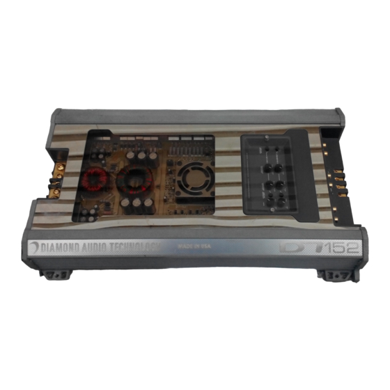
Advertisement
LOWPASS ON/OFF
Pushing this button "IN" engages the Lowpass filter. Pushing this button
"OUT" will bypass the filter.
LOWPASS FREQUENCY
Turning this control sets the Lowpass crossover point from 50Hz (fully
counterclockwise) to 5kHz (fully clockwise).
HIGHPASS FREQUENCY
Turning this control sets the Highpass crossover point from 50Hz (fully
counterclockwise) to 5kHz (fully clockwise).
HIGHPASS ON/OFF
Pushing this button "IN" engages the Highpass filter. Pushing this button
"OUT" will bypass the filter.
X-OVER OUT
This crossover is fully independent. Signal can be parallel routed from
the CH 1/2 INPUTS (X-OVER INPUT SELECT button set to the "IN"
position) or be directly sent to this crossover via the AUX. X-OVER INPUT
RCA jacks (X-OVER INPUT SELECT button set to the "OUT" position).
This configuration allows the AUX. crossover to be used with a separate
amplifier not equipped with its own on-board crossover for the ultimate in
system flexibility.
Note: By engaging both Highpass and Lowpass filters and setting the desired
crossover points, a Bandpass filter can be created:
AUXILIARY CROSSOVER
Signal can be routed from the channel 1/2 INPUTS (X-OVER INPUT
SELECT button set to the "IN" position) or combined with the CH 3/4
INPUTS (X-OVER INPUT SELECT button set to the "OUT" position).
These signals can then be processed by the third (AUXILIARY) crossover.
This additional independent crossover can be used with a separate amplifier
not equipped with its own on-board crossover for the ultimate in
system flexibility.
10
D7 CROSSOVER FREQUENCIES
Diamond Audio D7 Professional Reference Series Amplifiers feature fully
variable crossovers. The frequency control knobs (located in the tray on the
top of the amplifier) are labeled 50Hz when the knob is rotated fully counter-
clockwise (left) and 5kHz when rotated fully clockwise (right).
To make basic setting of the crossover frequencies a little easier, we've
come up with the following rotational diagram:
HIGHPASS/LOWPASS
FREQUENCY
Notice that the outer most circle of numbers (1:00, 2:00, etc.) represent
numbers as they appear on the face of a clock. The number underneath each
"hour" designation on the simulated clock face is the approximate crossover
frequency at that position.
BRIDGING
All pairs of Diamond Audio D7 amplifier channels are capable of being
bridged to a 4 Ohm mono output. Creation of the mono channel is accomp-
lished by using the left channel positive (+) output connection of the amplifier
for the speaker positive and the right channel negative (-) output connection
of the amplifier for the speaker negative.
11
Advertisement
Table of Contents

Summary of Contents for Diamond Audio D7
- Page 1 Bandpass filter can be created: BRIDGING All pairs of Diamond Audio D7 amplifier channels are capable of being bridged to a 4 Ohm mono output. Creation of the mono channel is accomp- lished by using the left channel positive (+) output connection of the amplifier for the speaker positive and the right channel negative (-) output connection of the amplifier for the speaker negative.
- Page 2 6VRMS. amplifier inputs. Rotating this control to the “MIN” mark (counterclockwise) configures your D7 amplifier to accept input voltages as high as 12V RMS with AUX. X-OVER INPUT the -12dB button pushed “IN” (see “RCA INPUT” drawing on page 12). This These RCA jacks allow you independent access to the AUX.
-
Page 3: Speaker Wiring
CROSSOVERS All Diamond Audio D7 amplifiers employ the most flexible internal crossover sections currently available in mobile audio. They feature third-order 18dB/ octave Butterworth filters. These filter networks sum to a flat response at their -3dB break points. - Page 4 Only the maximum output power is affected, and only until the heat sink cools down. Under no conditions will the D7 Series amplifiers have to shut off completely.
-
Page 5: Basic Troubleshooting
Run this wire from your source unit to the amplifiers REMOTE connection. Strip approximately 1/2 inch of insulation from the wire. Insert the wire into the terminal, and tighten the Allen screw. Your D7 Professional Amplifier has no output. -
Page 6: Amplifier Block Diagram
Your D7 Professional Reference Series Amplifier is designed to accept up to 4 gauge power and ground cable when using the Direct (stripped wire end) Connection method. -
Page 7: System Diagram
Basic Biamp System: Dual 2 Channel Amplifiers Your new D7 amplifier features adjustable mounting flanges. Should they need D7 two channel amplifier to be moved to a different location, remove the self-tapping screws on the Source: Front RCA outputs bottom of each mounting flange. -
Page 8: Installation
Channels 1/2 Bandpass to a pair of midbass drivers A WORD ABOUT PROFESSIONAL INSTALLATION… D7 two channel amplifier We, the folks at Diamond Audio, highly advise the use of a factory authorized Source: Rear RCA outputs installation technician. System performance ultimately depends on proper Channels 1/2 Highpass to a pair of installation. -
Page 9: Fuse Recommendations
Butterworth FUSE RECOMMENDATIONS D7 Professional Reference Series Amplifiers, by design, require external fusing. Research has shown that a circuit board mounted fuse can create a drop in available DC voltage at the input of the power supply resulting in increased current draw. -
Page 10: Specifications
Two Channel System with Symmetrical Topology, Fully Regulated, Triple-Split-Rail Power Supply Three Bridged Amplifiers Isolated Input Section Utilizing “Quasi-Differential” D7 two channel amplifier Instrumentation Amplifier Technology Channels 1/2 Highpass & Bridged to a Up To 12VRMS Input Signal Voltage Capability (With -12dB Attenuator)


Need help?
Do you have a question about the D7 and is the answer not in the manual?
Questions and answers