Advertisement
Instructions–Parts List
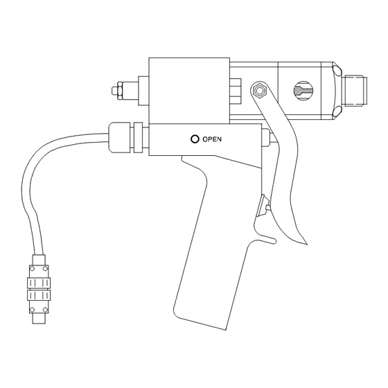
AIR OPERATED, SINGLE COMPONENT DISPENSE VALVE
1K Ultra–Litet
For dispensing a wide variety of single component sealants and adhesives.
4000 psi (28 MPa, 276 bar) Maximum Fluid Working Pressure
120 psi (0.84 MPa, 8.4 bar) Maximum Air Inlet Pressure
See page 2 for Table of Contents
Part No. 965766
Stainless Steel Wetted Parts, Machine
Mount Valve
Part No. 965767
Aluminum Wetted Parts, Hand–held
Valve with internal air switch
Part No. 965768
Aluminum Wetted Parts, Hand–held
Valve with electric switch for remote
operation
Part No. 965786
Aluminum Wetted Parts, Automatic
Machine Mount Valve
Part No. 243482
Stainless Steel Wetted Parts,
Precision Swirl Orbiter Mounted with
Nozzle Accessory
Part No. 243666
Stainless Steel Wetted Parts,
PrecisionFloR Control Valve
Machine Mount Valve
Important Safety Instructions
Read all warnings and instructions in this manual.
Save these instructions.
Model 965768 shown
308876K
8370A
Advertisement
Table of Contents

Related Manuals for Graco 1K Ultra–Lite 243482

Summary of Contents for Graco 1K Ultra–Lite 243482
- Page 1 Aluminum Wetted Parts, Hand–held Valve with electric switch for remote operation Part No. 965786 Aluminum Wetted Parts, Automatic Machine Mount Valve Part No. 243482 Stainless Steel Wetted Parts, Precision Swirl Orbiter Mounted with Nozzle Accessory Part No. 243666 Stainless Steel Wetted Parts,...
- Page 2 Table of Contents Warnings ........Features .
- Page 3 EQUIPMENT MISUSE HAZARD Equipment misuse can cause the equipment to rupture or malfunction and result in serious injury. INSTRUCTIONS D This equipment is for professional use only. D Read all instruction manuals, tags, and labels before operating the equipment. D Use the equipment only for its intended purpose. If you are uncertain about usage, call your Graco distributor.
-
Page 4: Fire And Explosion Hazard
FIRE AND EXPLOSION HAZARD Improper grounding, poor ventilation, open flames or sparks can cause a hazardous condition and result in a fire or explosion and serious injury. D Ground the equipment and the object being sprayed. Refer to Grounding on page 6. D If there is any static sparking or you feel an electric shock while using this equipment, stop dis- pensing immediately. -
Page 5: Features
D Adjustable forward travel to reduce material surge when valve opens D Severe-Dutyt needle and seat for longer operating life D Lubricated packings for longer seal life D Lightweight construction reduces operator/machinery fatigue 4 Control Configurations 1/8 npt(f) ported manifold block Direct solenoid mount with speed control Handle kit with 4-way air valve Handle kit with electric switch... -
Page 6: Installation
NOTES: D Reference numbers and letters in parentheses in the text refer to the callouts in the figures and drawings. D Accessories are available from your Graco representative. If you supply your own accessories, be sure they are adequately sized and pressure-rated to meet the system’s requirements. - Page 7 Connections D The fluid inlet is 1/4 npt(f). D The fluid outlet is 1/4 npt(f) or 3/4–16 unf(m). D Air inlets are 1/8 npt(f). D See Accessories, page 25, to order air control valves and tubing. Electric Switch Hand Held Valve Install a remote 4-way air control valve to operate the valve.
-
Page 8: Operation
WARNING COMPONENT RUPTURE HAZARD To reduce the risk of over-pressurization, which can cause component rupture and serious injury, never exceed 3000 psi (21 MPa, 207 bar) fluid pressure, or 120 psi (0.84 MPa, 8.4 bar) air pressure to the valve. Pressure Relief Procedure WARNING SKIN INJECTION HAZARD... -
Page 9: Operation
Air Switch Hand Held Valve The valve operation is such that there are only two valve conditions: either fully open or fully closed. The valve is opened and closed by the internal air control valve. Trigger the gun to open the valve. Release the trigger to close the valve. -
Page 10: Troubleshooting
WARNING SKIN INJECTION HAZARD To reduce the risk of serious injury whenever you are instructed to relieve pressure, always follow the Pressure Relief Procedure on page 8. PROBLEM CAUSE Valve does not open Insufficient air pressure Air not exhausted from behind air cylin- der piston Shaft adjustment too far closed Valve does not close... - Page 11 (Models 965766, 965767, 965768, and 965786 only) WARNING SKIN INJECTION HAZARD To reduce the risk of serious injury whenever you are instructed to relieve pressure, always follow the Pressure Relief Procedure on page 8. Disassembly 1. Relieve all air and fluid pressure. 2.
- Page 12 (Models 965766, 965767, 965768, and 965786 only) Reassembly Air Cylinder Section 1. Lubricate the shaft o-rings (4) and the bearings (5) with grease supplied in the repair kit. Insert o-rings into the air cylinder (1) and air cap (11) cavities. See Fig.
- Page 13 (Models 965766, 965767, 965768, and 965786 only) Air Valve (if equipped) 1. Insert the spring (51) into the housing (50). 2. Lubricate and install an o-ring (46) into the housing. 3. Install a spacer (52), internal bevel first, into the housing.
- Page 14 (Models 965766, 965767, 965768, and 965786 only) 8375B 28, 29 20 21 22 39 13, 14 9 10 19 18 Tighten to 15–20 in-lb (1.7–2.2 NSm). The shaft should hang with some play to be self-aligning in the bearing. Tighten to 15–20 in-lbs (1.7–2.2 NSm). Tighten oppositely and evenly to 40–45 in-lbs (4.5–5 NSm).
- Page 15 Notes 308876...
- Page 16 (Models 965766, 965767, 965768, and 965786 only) 308876 Parts (965766 & 965786 only) 28, 29 8371A...
- Page 17 } Use Loctite Primer N7649 and Loctite TL242, 243, or equivalent (“blue” Loctite) when assembling this part. n Use anti–seize lubricant (Loctite 56765 or equivalent) when assembling 965766 and 965786. Use Loctite TL242, 243, or equivalent (“blue” Loctite) when assembling 243482 and 243666. Qty. 308876...
- Page 18 Parts (965768 only) 8375B 8370A (965767 only) 8372A 308876...
- Page 19 5. Remove the seat (25), gasket (38), and o-ring (39). Service (Models 243482 and 243666 only) 6. Remove the two fluid housing screws (23) and remove the fluid housing (26). Remove the primary fluid seal (22) from the fluid housing (26).
- Page 20 5. Orient the air inlet manifold (2) (if used) as shown. Match the gasket openings to the air ports. 308876 Service (Models 243482 and 243666 only) Fluid Section 1. Lubricate the bearing (21), o-ring (16) and cup seal (20). Put the o-ring (16) on the bearing. Carefully insert the seal (20) into the bearing recess, with the lips of the o-ring facing into the bearing.
- Page 21 Lubricate with grease supplied in the repair kit. Tighten to 15–20 in lbs (17–22 NSm) Apply Loctite Primer N7649 and Loctite TL242, 243, or equivalent (“blue” Loctite). Fig. 6 Parts (Models 243482 and 243666 only) 38 25 Model 243482 308876...
- Page 22 308876 Parts (Models 243482 and 243666 only) Model 243482 28, 29 8371A...
- Page 23 Model 965767 Hand Held Valve with Pneumatic Trigger Aluminum wetted parts See page 16 for illustration of items 1–44. See page 18 for illustration of items 46–62. Ref. Part No. Description 626702 HOUSING, air cylinder 626068 SHAFT, air cylinder 156454 O-RING, 010 buna-n 551181 BEARING, air cylinder...
- Page 24 Model 965768 Hand Held Valve with Electric Switch Aluminum wetted parts See page 16 for illustration of items 1–44. See page 18 for illustration of items 53–63. Ref. Part No. Description 626702 HOUSING, air cylinder 626068 SHAFT, air cylinder 156454 O-RING, 010 buna-n 551181 BEARING, air cylinder...
-
Page 25: Accessories
Plastic Tube Fittings to Connect Air Signals Tube OD 1/8 NPT (M) Straight 1/8 in. 5/32 in. 1/4 in. Tube OD 1/4 NPT (M) Straight 5/32 in. 1/4 in. Plastic Tubing for Air Signal Lines Part No. Description 513063 1/8 in. O.D. Nylon 514607 5/32 in. -
Page 26: Part
Fluid Nozzles Zinc-plated steel nozzles, 1/8 npt* Part No. Orifice Length 607665 0.125 in. (3.17 mm) 2 in. (51 mm) 161505 0.09 in. (2.28 mm) 2 in. (51 mm) 164799 0.055 in. (1.39 mm) 2-1/8 in. (54 mm) Requires a 1/8 npt(f) bushing. Order 168683 Nozzle Bushing. -
Page 27: Technical Data
Category Maximum Fluid Pressure Maximum Cylinder Air Pressure Air inlets (open and close ports) Fluid Inlet Fluid Outlet Fluid Viscosity Range Snuffer Action Fluid Section Divorced Air Cylinder Weight Aluminum Valve Stainless Steel Valve Handle Kit Wetted Parts Aluminum Valve Stainless Steel Valve Severe-duty Components Shaft... - Page 28 6.13 in. (155.7 mm) 1.42 in. (36.07 mm) 2.25 in. (57.15 mm) Direct Mount Solenoid (optional) 308876 Dimensions 1.75 in. (44.45 mm) 5 in. (127 mm) 2.25 in. (57.15 mm) 0.88 in. (22.35 mm) 1.75 in. (44.45 mm) 3.5 in. (88.9 mm) 1.63 in.
- Page 29 Notes 308876...
-
Page 30: Graco Information
Graco Standard Warranty Graco warrants all equipment manufactured by Graco and bearing its name to be free from defects in material and workmanship on the date of sale to the original purchaser for use. With the exception of any special, extended, or limited warranty published by Graco, Graco will, for a period of twelve months from the date of sale, repair or replace any part of the equipment determined by Graco to be defective.
Need help?
Do you have a question about the 1K Ultra–Lite 243482 and is the answer not in the manual?
Questions and answers