
Related Manuals for Orion 3000


Summary of Contents for Orion 3000
- Page 1 Orion 3000 Wireless LAN Cable Modem User’s Guide Rev. 1.2a Firmware revision: 5.8.2004 April 14 , 2003...
-
Page 2: Table Of Contents
Contents 1. BEFORE YOU BEGIN ......................5 Understand the Wireless Cable Modem’s Features ..................5 Contact Your Local Cable Operator........................6 Prepare Your Area for Wireless Cable Modem Installation ................6 Gather Supplied and Required Items ......................... 6 2. INSTALLING THE MODEM USING WIRELESS.............8 Installing the Hardware ............................ - Page 3 7. TELNET COMMANDS.......................33 Debug..................................35 Image ..................................35 Ping ..................................36 Password ................................36 User-Level ................................37 Show..................................37 NVRAM................................44 TFTP..................................44 DHCP..................................44 Interfaces................................46 NAT..................................48 One to one mapping..........................49 Port forwarding setting ..........................49 NAT static ip .............................. 50 NAT static gateway ...........................
- Page 4 Security WEP ............................59 WEP Key ..............................60 Access Permission ............................. 60 Submit ................................ 60 User’s Guide...
-
Page 5: Before You Begin
1. Before You Begin Your new wireless cable modem provides high-speed wireless access to the Internet by using IEEE 802.11b wireless standard and an active Internet Connection through your cable service provider. This user guide describes how to set up and use the wireless cable modem. Before installing the wireless cable modem, you should read this user guide to ensure proper wireless cable modem operation. -
Page 6: Contact Your Local Cable Operator
Contact Your Local Cable Operator Before installing you new wireless cable modem, you must contact your local cable service provider to activate your Internet account. Be sure to have the wireless cable modem’s MAC address available, which can be found on the underside of the wireless cable modem. Prepare Your Area for Wireless Cable Modem Installation Before installing your wireless cable modem, you should first prepare your area. - Page 7 Wireless client drivers Wireless LAN Utility This user guide Not Supplied Verify that these items are available before beginning the installation: • If using the wireless cable modem’s USB port: o A PC running Windows 98 Second Edition (SE), Windows Me, Windows 2000, or Windows XP.
-
Page 8: Installing The Modem Using Wireless
Chapter 2 provides instructions for installing your wireless cable modem using the Wireless feature. Chapter 3 provides instructions for installing your wireless cable modem using the USB port. Chapter 4 provides instructions for installing your wireless cable modem using the Ethernet port. -
Page 9: Installing The Wireless Cable Modem Using The Usb Port
example, a wall that is 1 foot thick, at a 45-degree angle appears to be almost 2 feet thick. • Make sure PC's wireless client is connecting to right WLCM. Check the SSID of the WLCM and wireless client. 3. Installing the Wireless Cable Modem Using the USB Port This chapter explains the process for installing your cable modem using the USB port. - Page 10 3. You will see the following Welcome screen. 4. Click “Next>”. You will see the following Start screen. User’s Guide...
- Page 11 5. Click “Next>”. You will see the following ‘Complete’ screen. 6. Click “Finish”. You will see below screen, and then select ‘Yes.’ Now you can connect the User’s Guide...
-
Page 12: Installing The Hardware
USB cable to the PC by following next section instructions. Installing the Hardware This section explains how to connect the cable modem to the computer, wall outlet, and electrical outlet. To install the hardware: 1. Power off the computer 2. Connect one end of the coaxial cable to the cable modem’s cable connector. Connect the other end of the coaxial cable to the cable wall outlet. - Page 13 2. Insert the CD into the PC’s CD-ROM and click Next. You will see the following screen. 3. Select Search for the best driver for your device (Recommended). Then select Next. You will see the following screen. User’s Guide...
- Page 14 4. Check the CD-ROM drive check box and verify that the CD is in the CD-ROM drive. Click Next to have Windows search for the necessary driver files. You will see the following. 5. Select the updated driver (Recommended) Ambit USB Cable Modem and click next. You will see the following screen.
- Page 15 correct location of the driver files. DO NOT proceed if USB Composite Device is displayed in the above window. Contact your cable provider for further assistance. 6. Click Next. The computer automatically installs the necessary driver files. You may see the following screen. 7.
- Page 16 8. After files copying is done, you will see the following screen: 9. Click Finish to complete the installation. You will see the following screen. User’s Guide...
-
Page 17: Installing The Software Drivers In Windows Me Operating System
10. Choose Yes to restart your computer. 11. After the computer is rebooted, verify that the USB LED is lit on the front of you cable modem. If not, refer to the troubleshooting section later in this chapter. Installing the Software Drivers in Windows Me Operating System To install the cable modem software drivers using the Windows Me operating system: 1. - Page 18 3. Select Automatic search for a better driver (Recommended) and click Next. The computer automatically copies the necessary driver files from the CD. You will see the following screen. 4. Click Next. The computer automatically installs the necessary driver files. User’s Guide...
- Page 19 5. Click Finish after the computer has copied the necessary files. You will see the following screen. 6. Click Yes to restart the computer User’s Guide...
-
Page 20: Installing The Software Drivers In Windows 2000 Operating System
Installing the Software Drivers in Windows 2000 Operating System To install the cable modem software drivers using the Windows 2000 operating system: 1. Power on your PC. After your computer boots, Windows detects the cable modem. The Found New Hardware screen appears, followed by the Found New Hardware Wizard screen. - Page 21 4. Select Search for a suitable driver for my device (recommended. Then select Next. You will see the following screen User’s Guide...
- Page 22 5. Check the CD-ROM drive check box and verify that the CD is in the CD-ROM drive. Click Next to have Windows locate the necessary driver files. You will see the following screen. 6. Click Next to install the driver files for the cable modem. You will see the following screen.
-
Page 23: Installing The Software Drivers In Windows Xp Operating System
7. Click Finish to complete the installation. 8. After the installation is completed, verify that the USB LED is lit on the front of you cable modem. If not, refer to the troubleshooting section later in this chapter. Installing the Software Drivers in Windows XP Operating System 1. - Page 24 2. Choose the software automatically (Recommended). Click Next to continue. You will see the following screen. User’s Guide...
-
Page 25: Troubleshooting The Usb Installation
3. Click Finish to complete the installation. Troubleshooting the USB Installation None of the LEDs are on when I power on the Wireless LAN Cable Modem. Check the connection between the power adapter and the cable modem. Power off the Wireless LAN Cable Modem and wait for 5 Seconds and power on the modem again. - Page 26 4. Select USB Composite Device and click Remove 5. Click Refresh The Add New Hardware Wizard window appears, displaying the device name USB Composite Device. Refer to the proper operating system instructions in this chapter for information on reinstalling the driver properly. All of the LEDs on the front of my modem look correct, but I cannot access the Internet.
-
Page 27: Uninstalling The Usb Driver
modem. • Power cycle the cable modem by removing the power adapter from the electrical outlet and plugging it back in. Wait several minutes for the cable modem to re-establish communications with your cable service provider. • Remove any other USB devices from your computer and connect the cable modem’s USB cable directly to the USB port on your computer. -
Page 28: Installing The Hardware
configuring TCP/IP. After installed the hardware, your computer can connect the wireless cable modem directly by using Network Interface Card. Unlike USB installation, there is no needed for software installation for the Ethernet connection. Installing the Hardware This section explains how to connect the wireless cable modem to the computer, wall cable outlet, and electrical outlet. -
Page 29: Wireless Cable Modem Leds And Connectors
X over the NIC in the Network Adapters field. If you see either one, you may have an IRQ conflict. Refer to the manufacturer’s documentation or you cable service provider for further assistance. • Verify that TCP/IP is the default protocol for your network interface card (NIC) •... -
Page 30: Connectors On The Back Of The Modem
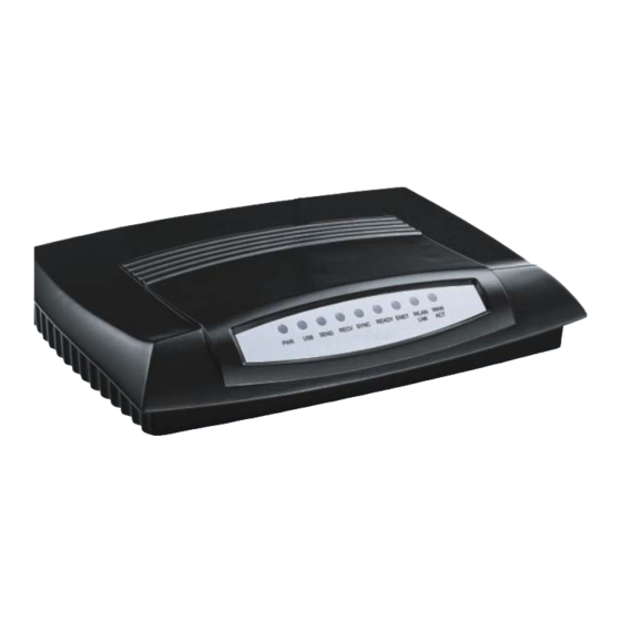
• PWR: Indicates that the wireless cable modem has successfully completed internal power-on tests. • USB: Indicates connectivity between the USB port on the wireless cable modem and the PC’s USB port. • ENET: Indicates connectivity between the Ethernet port on the wireless cable modem and the Ethernet port on the PC or Mac. -
Page 31: Product Specifications
1. ENET Port: This is where you plug the included Ethernet cable. The other end connects to the Ethernet Jack on the PC or NIC. This is not needed when using the USB port or wireless feature. 2. USB Port: This is where you plug the included USB cable. The other end connects to the USB port on your PC. - Page 32 MIBs Support RFC1213, RFC2011, RFC2012, MIB-2, Interface and Cable, RFC2013,RFC2669, RFC2670, Security MIB support RFC2233, RFC1907, RFC1493, draft-ietf-ipcdn-mcns-bpi-mib-01 Syslog client Send event to syslog server Description Specification Dimensions (H x W x D) ) 2.0 x 13.0 x 19.5cm Linear: AC 100 ~ 120 Volt (50 ~ 60 Hz) AC Power (Input) or AC 220 ~ 240 Volt (50 ~ 60 Hz) Switching: AC 100 ~ 240 Volt (Optional)
-
Page 33: Telnet Commands
7. Telnet commands The Cable Router telnet Login and Password: Login: Password: ** Note: Default Wireless LAN Cable Modem Router Telnet IP address is 192.168.100.1 Getting Help Entering a question mark (?) at the system prompt displays a list of commands for each command mode. - Page 34 To list keywords or arguments, enter a question mark (?) in place of a keyword or argument. Include a space before the ?. This form of help is called command syntax help, because it reminds you which keywords or arguments are applicable based on the command, keywords, and arguments you already have entered.
-
Page 35: Debug
Debug debug Display corresponding message, the protocol debug just show packet information send to or receive from RF interface. CM>debug ? console Display console message IP information dhcp DHCP protocol information ARP information Layer 2 information NAT translation information CM>debug ip ? TCP information UDP information icmp... -
Page 36: Ping
Download the specified firmware image name from TFTP server and store in as “image 1” or “image 2”. If {1|2} is not specified, cable modem will upgrade the other image. (If cable modem boot with image 2, it will upgrade image 1) Example: CM>image upgrade 1 Downloading ram.compress from 172.146.1.177... -
Page 37: User-Level
Change the password of accessing Telnet command. Example: CM>pwd admin Old password: New password: Reconfirm: Change password successfully. User-Level user-level [user name] {1-90} Change the password of accessing Telnet command. Example: CM>user-level admin 90 password: Change user admin access level to 90. Change user access level successfully. - Page 38 show version Display hardware and software reversion and board ID. Example: CM>show version Hardware revision: 4.3 Board ID: T60C237.30.01_TW Serial number: T10245000489 Bootcode revision: 3.5.7 Software revision: 5.8.2003 Web Page revision: 1.0.1 Software build time: Nov 26 2002 17:57:19 show ip route Display routing table Example: CM>show ip route...
- Page 39 IP address 30.0.0.9 subnet-mask 255.255.255.248 Link status: link Mode: 10Mbps, half-duplex RIP status: Enable RIP send version: 2 show interface cable Display cable interface information Example: CM>show interface cable Interface Cable MAC address: 0008.0E86.1118 IP address 10.71.135.99 subnet-mask 255.255.240.0 Downstream information FEC Lock : Locked Downstream Frequency : 561000000 Hz Downstream Modulation : 64 QAM...
- Page 40 Interface USB USB-Host MAC address: 0002.8A0E.ECCA Speed: 12Mbps Link status: disconnect show interface wireless Display ethernet interface configuration Example: CM>show interface wireless Interface Wireless Speed: 11Mbps SSID: WLCM HOST: WLCM Channel: 11 WEP mode: Disable show running-configuration Display system running information Example: CM>show running-configuation Interface USB...
- Page 41 Upstream Symbol Rate : 2560 ksym/sec Upstream Frequency : 28688000 Hz Upstream Mini-Slot Size : 8 Upstream Burst Descriptor : Initial Periodic request(1) Ranging(3) Ranging(4) shortData(5) longData(6) Modulation Type QPSK QPSK QPSK QPSK QPSK Differential Preamble Length Preamble Value FEC Error no FEC FEC Codeword Scrambler Seed...
- Page 42 Web access control CPE interface web access enable. Cable interface web access enable. Access List is empty show cpe-info Display CPE information Example: CM>show cpe-info Port 0003.4793.064B 30.0.0.10 Ethernet show downstream Display downstream information Example: CM>show downstream FEC Lock : Locked Downstream Frequency : 561000000 Hz Downstream Modulation : 64 QAM Downstream Interleave Depth : 32...
- Page 43 FEC Codeword Scrambler Seed Maximum Burst Size 0 Guard Time Size Last Codeword fixed fixed fixed fixed fixed Scrambler on/off show nat config Display all settable NAT/PAT information Example: CM>show nat config NAT : Enable WAN SETUP : NAT public IP configuration : Automatically NAT public IP address : 68.5.203.15 Subnet Mask : 255.255.254.0 NAT public Gateway IP address : 68.5.202.1 LAN SETUP :...
-
Page 44: Nvram
CM>show user Index User Name From Alive(sec) Idle(sec) admin 192.168.100.2 show access-list Display access list information Example: CM>show access-list Access List ID Control Address 41 Permit 00D0.5900.0000, hardware address mask FFFF.FF00.0000 42 Permit 0008.0E00.0000, hardware address mask FFFF.FF00.0000 1 Permit 192.168.100.0, wildcard bits 0.0.0.16 21 Permit 64.168.39.0, wildcard bits 0.0.0.8... - Page 45 Enable/disable dhcp server dhcp lease-time { 30-2147483647 seconds} Set dhcp server ip lease time dhcp dns add {1~4} {ip address} Set dhcp server dns ip address, it allows maximum 4 dns setting. dhcp dns delete {1~4/all} Remove dhcp server dns ip address setting. Note: if NAT is enabling, the following DHCP command can bet set dhcp ip-pool add {start IP} {end ip} Set dhcp server ip pool range...
-
Page 46: Interfaces
Example: CM>dhcp reserve-mac add 192.168.100.4 0002.8A25.251D CM>show dhcp TFTP Server IP address : 172.19.89.19 Cable Modem IP address : 10.71.135.99 Configuration file : DEF001.cfg Lease time : 86400 (secs) UTC time offset : -28800 (secs) SystemLog Server IP address : 172.19.89.19 Router IP address : 10.71.128.1 SubnetMask : 255.255.240.0 DHCP server enable... - Page 47 interface ethernet mac-address {mac address} Assign mac-address for ethernet interface CM>interface ethernet mac-address 0008.0E86.1118 CM>show interface ethernet Interface Ethernet MAC address: 0008.0E86.1118 IP address 192.168.100.1 subnet-mask 255.255.255.224 Link status: disconnect interface ethernet shutdown Ethernet interface shutdown interface ethernet startup Ethernet interface startup interface cable upstream channel {id} Change upstream channel ID interface cable downstream preset {frequency}...
-
Page 48: Nat
Example: CM>interface wireless ssid Ambit Set SSID to Ambit interface wireless host {host name} Set Wireless LAN Cable Router Access Point host name Example: CM>interface wireless host Conference-Room Set host to Conference-Room interface wireless channel {1~11} Set Wireless LAN Cable Router Access Point channel Example: CM>interface wireless channel 11 Set Channel to 11... -
Page 49: One To One Mapping
ip nat {enable/disable} Enable/disable NAT/PAT gateway function nat timer {tcp/udp/gre/icmp} {1~86400 sec} Set aging time for different protocol session One to one mapping nat static ipmapping add { private ipaddress} { global ipaddress} Set NAT one to one mapping table Example: CM>nat static ipmapping add 68.5.203.16 192.168.100.22 Set global IP 68.5.203.16 to private IP 192.168.100.22... -
Page 50: Nat Static Ip
Set NAT/PAT Port forwarding table CM>nat static portmapping add 21 192.168.100.23 ftp CM>show nat config NAT : Enable WAN SETUP : NAT public IP configuration : Manually Static NAT public IP address : 68.5.203.15 Subnet Mask : 255.255.254.0 Static NAT public Gateway IP address : 68.5.202.1 LAN SETUP : Ethernet interface IP address 192.168.100.1 subnet-mask 255.255.255.224 NAT DHCP Server Pool Table :... -
Page 51: Nat Static Gateway
Example: CM>nat static ip enable Static IP will be enabled after "reset" command. nat static ip {ipaddress} mask (mask) Set static IP and network mask for NAT/PAT Example: CM>nat static ip 68.5.203.15 mask 255.255.254.0 Set NAT public IP to 68.5.203.15, subnet mask to: 255.255.254.0 NAT static gateway nat static gateway {ipaddress} Set static router address... - Page 52 Wireless LAN Cable Router IP address. The standard MAC access list performs frame filtering based on source MAC address from the CPE host(s). Basically, the access list works as a source address packet filter, if the access list is empty, the cable router will forward any packet, if access list is not empty, packet filtering will be enforced according to the access list(s).
- Page 53 Download the Wireless Cable Router configuration from remote tftp server. The configuration file must be text file. write Write configuration to NVRAM reset Reboot cable modem quit Disconnect telnet. User’s Guide...
-
Page 54: Web User Interface
8. Web User Interface Accessing the Web User Interface 1. The PC connected to the wireless cable modem must support TCP/IP connection and dynamic DHCP IP address acquisition, and must have a web browser installed. 2. Open the web browser and set the URL location as: http://192.168.100.1 Web User Interface Home Page A main menu is shown at the top of the pages and the user can select different options to view wireless cable modem information. -
Page 55: Cable Modem Status
Cable Modem Status User’s Guide... -
Page 56: Downstream
Downstream Upstream User’s Guide... -
Page 57: Upstream Burst
Upstream Burst Operation Parameters User’s Guide... -
Page 58: Event Log
Event Log User’s Guide... -
Page 59: Wireless Configuration
Wireless Configuration SSID • You can input SSID to group your wireless network. The wireless clients that have the same SSID can communicate with others. Host • In Host item, you can define the wireless cable modem name. Channel • There are 11 channels available for US. You also can specific wireless communication channel in Channel section. -
Page 60: Access Permission
WEP Key • 64 bits WEP requires a 10 Hexadecimal digits key, and 128 bits WEP key needs a 26 Hexadecimal digits key. Access Permission • Access permission is set for “Allow everyone access” by default. • If Access Permission is set for “only allow access if on this list”, only CPE with matching MAC address from the list is allowed to access.
Need help?
Do you have a question about the 3000 and is the answer not in the manual?
Questions and answers