Table of Contents
Advertisement
Quick Links
Download this manual
See also:
Owner's Manual
Advertisement
Table of Contents
Troubleshooting

Related Manuals for Orion 3000


Summary of Contents for Orion 3000
- Page 1 Orion 3000 Wireless LAN Cable Modem User’s Guide MSOs Rev. 1.3a Firmware 5.8.3003 May 9 , 2003...
-
Page 2: Table Of Contents
Contents 1. BEFORE YOU BEGIN ......................6 Understand the Wireless Cable Modem’s Features ..................6 Contact Your Local Cable Operator........................6 Prepare Your Area for Wireless Cable Modem Installation ................7 Gather Supplied and Required Items ......................... 7 2. INSTALLING THE MODEM USING WIRELESS.............8 Installing the Hardware ............................ - Page 3 Debug..................................32 Image ..................................32 Ping ..................................33 Tracert .................................. 33 Password ................................34 User-Level ................................34 Show..................................34 NVRAM................................41 TFTP..................................41 Host-name ................................41 DHCP..................................42 Interfaces................................44 NAT..................................46 One to one mapping..........................46 Port forwarding setting ..........................47 NAT static ip ..............................
- Page 4 Cable Modem Status ............................54 Downstream ................................. 55 Upstream ................................55 Upstream Burst ..............................56 Operation Parameters ............................56 Event Log ................................57 Wireless Configuration............................58 Wireless ..............................58 SSID ................................58 HOST................................58 Channel ..............................58 WEP Encryption ............................59 Key Format..............................
- Page 5 User’s Guide...
-
Page 6: Before You Begin
1. Before You Begin Your new wireless cable modem provides high-speed wireless access to the Internet by using IEEE 802.11b wireless standard and an active Internet Connection through your cable service provider. This user guide describes how to set up and use the wireless cable modem. Before installing the wireless cable modem, you should read this user guide to ensure proper wireless cable modem operation. -
Page 7: Prepare Your Area For Wireless Cable Modem Installation
Prepare Your Area for Wireless Cable Modem Installation Before installing your wireless cable modem, you should first prepare your area. To do this: 1. Locate your cable outlet and ensure that it is located within proper distance of your wireless cable modem and computer. Be sure not to bend the cable as this may strain the connector and cause damage. -
Page 8: Installing The Modem Using Wireless
o An active USB port on your PC. • If using the wireless cable modem’s Ethernet port: o A PC running Windows 95 (or later) operating system or a Macintosh computer running system 7.6 (or later) operating system o An active Ethernet port on your PC or Macintosh •... -
Page 9: Installing The Hardware
Installing the Hardware This section explains how to connect the wireless cable modem to the computer, wall cable outlet, and electrical outlet. To install the hardware: 1. Power off the computer 2. Connect one end of the coaxial cable to the wireless cable modem’s cable connector. Connect the other end of the coaxial cable to the cable wall outlet. - Page 10 Using the USB port allows you to install the cable modem more quickly and easily than using the Ethernet port, because you do not have to install and configure a network interface card (NIC). USB, however, only enables you to connect one computer to the cable modem. Using the Ethernet port allows to you connect multiple computers to a cable modem through the use of additional equipment which is not included.
- Page 11 4. Click “Next>”. You will see the following Start screen. 5. Click “Next>”. You will see the following ‘Complete’ screen. User’s Guide...
-
Page 12: Installing The Hardware
6. Click “Finish”. You will see below screen, and then select ‘Yes.’ Now you can connect the USB cable to the PC by following next section instructions. Installing the Hardware This section explains how to connect the cable modem to the computer, wall outlet, and electrical outlet. -
Page 13: Installing The Software Drivers
Installing the Software Drivers This section explains how to install the software drivers that your PC requires for the cable modem to operate. Installing the Software Drivers in Windows 98 SE Operating System CAUTION: You must install the drivers located on the CD that ships with your cable modem. - Page 14 3. Select Search for the best driver for your device (Recommended). Then select Next. You will see the following screen. 4. Check the CD-ROM drive check box and verify that the CD is in the CD-ROM drive. Click Next to have Windows search for the necessary driver files. You will see the following.
- Page 15 5. Click Next. The computer automatically installs the necessary driver files. You may see the following screen 6. If the above screen appears, you must insert the Windows 98 CD so that Windows can copy the remaining files. User’s Guide...
- Page 16 7. Wait for Windows to complete copying the remaining files. 8. Click Finish to complete the installation. You will see the following screen. 9. Choose Yes to restart your computer. 10. After the computer is rebooted, verify that the USB LED is lit on the front of you cable modem.
-
Page 17: Installing The Software Drivers In Windows Me Operating System
Installing the Software Drivers in Windows Me Operating System To install the cable modem software drivers using the Windows Me operating system: 1. Power on your PC. After your computer boots, Windows detects the cable modem. The Found New Hardware screen appears, followed by the Found New Hardware Wizard screen. - Page 18 4. Check the CD-ROM drive check box and verify that the CD is in the CD-ROM drive. Click Next to have Windows search for the necessary driver files. You will see the following 5. Click Finish after the computer has copied the necessary files. You will see the following screen.
-
Page 19: Installing The Software Drivers In Windows 2000 Operating System
6. Click Yes to restart the computer Installing the Software Drivers in Windows 2000 Operating System To install the cable modem software drivers using the Windows 2000 operating system: 1. Power on your PC. After your computer boots, Windows detects the cable modem. The Found New Hardware screen appears, followed by the Found New Hardware Wizard screen. - Page 20 2. Insert the CD into the PC’s CD-ROM Drive and click Next. You will see the following screen. 3. Select Search for a suitable driver for my device (recommended. Then select Next>. You will see the following screen 4. Check the CD-ROM drive check box and verify that the CD is in the CD-ROM drive. User’s Guide...
- Page 21 Click Next to have Windows locate the necessary driver files. You will see the following screen. 5. Click Next to install the driver files for the cable modem. You will see the following screen. User’s Guide...
-
Page 22: Installing The Software Drivers In Windows Xp Operating System
7. Click Finish to complete the installation. 8. After the installation is completed, verify that the USB LED is lit on the front of you cable modem. If not, refer to the troubleshooting section later in this chapter. Installing the Software Drivers in Windows XP Operating System 1. -
Page 23: Troubleshooting The Usb Installation
3. Click Finish to complete the installation. Troubleshooting the USB Installation None of the LEDs are on when I power on the Wireless LAN Cable Modem. Check the connection between the power adapter and the cable modem. Power off the Wireless LAN Cable Modem and wait for 5 Seconds and power on the modem again. - Page 24 4. Select USB Composite Device and click Remove 5. Click Refresh The Add New Hardware Wizard window appears, displaying the device name USB Composite Device. Refer to the proper operating system instructions in this chapter for information on reinstalling the driver properly. All of the LEDs on the front of my modem look correct, but I cannot access the Internet.
-
Page 25: Uninstalling The Usb Driver
re-establish communications with your cable service provider. • Remove any other USB devices from your computer and connect the cable modem’s USB cable directly to the USB port on your computer. • If you are using a cable splitter, try removing the splitter and connect the cable modem directly to the cable wall outlet. -
Page 26: Troubleshooting The Ethernet Installation
outlet, and electrical outlet. To install the hardware: 1. Power off the computer 2. Connect one end of the coaxial cable to the wireless cable modem’s cable connector. Connect the other end of the coaxial cable to the cable wall outlet. Be sure not to bend or over tighten the cables as this may strain the connector and cause damage. -
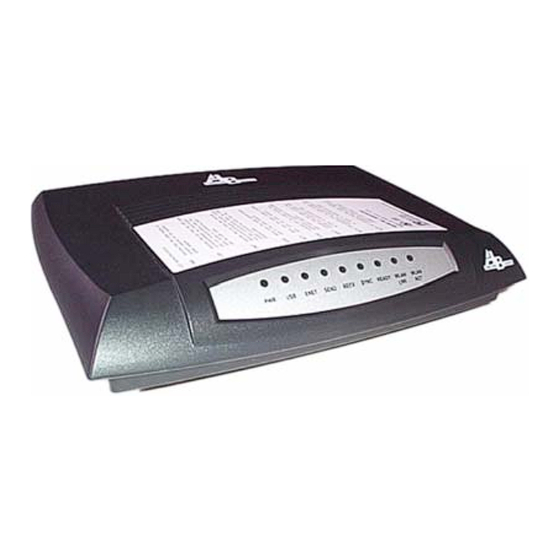
Page 27: Wireless Cable Modem Leds And Connectors
• If the POWER, ENET, SYNC, and READY LEDs are solidly lit, the wireless cable modem is working properly. Try restarting the computer so that is could re-establish a connection with the wireless cable modem. • Power cycle the wireless cable modem by removing the power adapter from the electrical outlet and plugging it back in. -
Page 28: Connectors On The Back Of The Modem
wireless cable modem is transferring or receiving data over the Ethernet cable. • SEND: Indicates that data is being transmitted from the wireless cable modem to the cable network. • RECV: Indicates that data is being received from the cable network. •... -
Page 29: Product Specifications
6. Product Specifications This chapter describes the cable modem’s operating and hardware specifications. Item Downstream (Receiver) Upstream (Transmitter) Frequency Range 88MHz ~ 860MHz 5MHz ~ 42MHz Channel Bandwidth DOCSIS: 6MHz 200K, 400K, 800K, 1.6M, 3.2MHz Modulation 64QAM/256QAM QPSK/16QAM Symbol Rate 5.057/5.361 Msymbols/sec 160, 320, 640, 1280, 2560 Ksymbols/sec Data Rate... -
Page 30: Telnet Commands
7. Telnet commands The Cable Router telnet Login and Password: Login: Password: ** Note: Default Wireless LAN Cable Modem Router Telnet IP address is 192.168.100.1 Getting Help Entering a question mark (?) at the system prompt displays a list of commands for each command mode. - Page 31 To list keywords or arguments, enter a question mark (?) in place of a keyword or argument. Include a space before the ?. This form of help is called command syntax help, because it reminds you which keywords or arguments are applicable based on the command, keywords, and arguments you already have entered.
-
Page 32: Debug
Debug debug Display corresponding message, the protocol debug just show packet information send to or receive from RF interface. CM>debug ? console Display console message IP information dhcp DHCP protocol information ARP information Layer 2 information NAT translation information CM>debug ip ? TCP information UDP information icmp... -
Page 33: Ping
Example: CM>image upgrade 1 Downloading ram.compress from 172.146.1.177 ....Download file size=596407 Board ID is U10C005.00.01_JP01 Compatible list is U10C005.00.01_US01 Match compatible list Update image 1... Reboot Cable Modem... image use {1|2} Activate and boot with the firmware stored in “image 1” or “image 2”. Ping ping {IP address} [-t] Ping specified IP address. -
Page 34: Password
10ms 10ms 10ms 172.21.1.252 10ms 10ms 10ms 192.168.55.254 20ms 10ms 10ms 211.23.52.161 60ms 70ms 0ms 172.21.1.252 0ms 211.22.38.2 0ms 172.21.1.252 0ms 168.95.2.162 0ms 211.22.33.27 0ms 210.65.161.89 0ms 202.39.83.130 0ms 202.39.83.65 0ms 202.39.82.17 0ms 216.115.100.158 0ms 216.115.101.42 0ms 66.218.71.198 trace complete Password pwd {user name} Change the password of accessing Telnet command. - Page 35 Lease time: 18000 (secs) UTC time offset: 28800 (secs) System Log Server IP address: 92.146.1.254 Router IP address: 10.146.1.254 Subnet Mask: 255.255.0.0 show version Display hardware and software reversion and board ID. Example: CM>show version Hardware revision: 4.3 Board ID: T60C237.30.01_TW Serial number: T10251000674 Bootcode revision: 3.5.7 Software revision: 5.8.3003...
- Page 36 CM>show interface cable Interface Cable MAC address: 0008.0E86.1118 IP address 10.71.135.99 subnet-mask 255.255.240.0 Downstream information FEC Lock : Locked Downstream Frequency : 561000000 Hz Downstream Modulation : 64 QAM Downstream Interleave Depth : 32 Downstream Receive Power Level : -1.18 dBmv Downstream SNR : 33.28 dB Upstream information Upstream Channel ID : 2...
- Page 37 HOST: WLCM Channel: 11 WEP mode: Disable show running-configuration Display system running information Example: CM>show running-configuation Hardware revision: 4.3 Board ID: T60C237.30.01_TW Bootcode revision: 3.5.7 Software revision: 5.8.3003 System up time is 0 days 00:01:34 System time is 2003-5-2 10:01:36 Host Name is empty Interface Cable MAC address: 0008.0E86.1118...
- Page 38 Interface Ethernet MAC address: 0002.8A0E.ECC9 IP address 192.168.100.1 subnet-mask 255.255.255.0 (nat-private) Link status: link Mode: 100Mbps, full-duplex Interface USB USB-Host MAC address: 0002.8A0E.ECCA Speed: 12Mbps Link status: disconnect Interface Wireless Speed: 11Mbps SSID: WLCM HOST: WLCM Channel: 6 WEP mode: Disable Firewall is enable Cable Modem mode : NAT NAT : Enable...
- Page 39 Access List is empty PPPoE forwarding disable. Number of CPE limitation MAC address limit: unlimited IP address limit: unlimited show cpe-info Display CPE information Example: CM>show cpe-info Port 0003.4793.064B 30.0.0.10 Ethernet show downstream Display downstream information Example: CM>show downstream FEC Lock : Locked Downstream Frequency : 561000000 Hz Downstream Modulation : 64 QAM Downstream Interleave Depth : 32...
- Page 40 Last Codeword fixed fixed fixed fixed fixed Scrambler on/off show nat config Display all settable NAT/PAT information Example: CM>show nat config NAT : Enable WAN SETUP : NAT public IP configuration : Automatically NAT public IP address : 68.101.124.80 Subnet Mask : 255.255.255.0 NAT public Gateway IP address : 68.101.124.1 LAN SETUP : Sub Ethernet interface IP address 192.168.100.1 subnet-mask 255.255.255.0...
-
Page 41: Nvram
Display access list information Example: CM>show access-list Access List ID Control Address 41 Permit 00D0.5900.0000, hardware address mask FFFF.FF00.0000 42 Permit 0008.0E00.0000, hardware address mask FFFF.FF00.0000 1 Permit 192.168.100.0, wildcard bits 0.0.0.16 21 Permit 64.168.39.0, wildcard bits 0.0.0.8 show cpe-limit Display CPE limit information Example: CM>show cpe-limit... -
Page 42: Dhcp
Example: CM>host-name set Customer1 Set host-name to"Customer1” Customer1> host-name delete Delete host-name. It will change the command prompt to CM>. tftp server {Server IP address} Establishes the IP address of the TFTP server for firmware download Example: CM>tftp server 92.146.1.250 Set TFTP Server to 92.146.1.250 DHCP dhcp {enable/disable}... - Page 43 dhcp ip-pool delete {1-20|all} Delete one/all ip-pool based on the index of ip-pool table. dhcp gateway {ip address} Set DHCP gateway ip address. dhcp reserve-mac add {ip address} {mac address} Reserve a specific private LAN ip address for a specific mac address. Example: CM>dhcp reserve-mac add 192.168.100.4 0002.8A25.251D CM>show dhcp...
-
Page 44: Interfaces
dhcp domain-name set {domain name} Set domain name manually. dhcp domain-name delete Delete domain name manually assigned. Interfaces interface ethernet address {ip address} mask {subnet netmask}{nat-private|””} Set ethernet interface IP address. Set ethernet interface IP address as nat-private gateway. Example: CM>interface ethernet address 192.168.100.1 mask 255.255.255.224 CM>show interface ethernet Interface Ethernet... - Page 45 interface cable shutdown Cable interface shutdown. interface cable startup Cable interface startup. interface usb shutdown USB interface shutdown. interface usb startup USB interface startup. interface wireless shutdown Wireless interface shutdown. interface wireless startup Wireless interface startup. interface wireless ssid {ssid name} Set Wireless LAN Cable Router Access Point SSID name.
-
Page 46: Nat
Example: CM>interface wireless wep 64bits key hex 1122334455 Set Wireless LAN Cable Router Access Point 64bits wep key to hexadecimal digital of 1122334455 interface wireless wep {disable|enable} Enable|disable Wireless LAN Cable Router Access Point wep key. interface wireless enhsecurity {disable|enable} Enable|disable broadcsting of SSID, if enable, a wireless client cannot obtain the SSID through passive scanning and authenticate without knowing the SSID. -
Page 47: Port Forwarding Setting
NAT public Gateway IP address : 68.5.202.1 LAN SETUP : Ethernet interface IP address 192.168.100.1 subnet-mask 255.255.255.224 NAT DHCP Server Pool Table : NAT DHCP server support 20 IP pools NAT DHCP server support 512 IP, Created 20 IP Pool Index Begin IP End IP 192.168.100.1 192.168.100.21... -
Page 48: Nat Static Ip
21 192.168.100.23 nat static portmapping delete {index/all} Remove the entry from the portmapping table Example: CM>nat static portmapping delete 1 Delete static portmapping index 1 NAT static ip nat static ip {enable|disable|ipaddress} Enable/disable NAT/PAT gateway function or assign global ip Example: CM>nat static ip disable Static IP will be disabled after "reset"... -
Page 49: Web-Access
ip nat {enable/disable} Enable/disable NAT/PAT function. Web-access web-access cpe {enable|disable} Enable|disable the CM web access via CPE interface. web-access cable {enable|disable} Enable|disable the CM web access via Cable interface. Access-list access-list {1~20|21~40|41~60|61~75} {deny|permit} {any|source IP|mac address} [wildcard bit] The standard access list performs packet filtering based on source IP address from the CPE host(s). The management access list performs packet filtering based on destination IP address matching the Wireless LAN Cable Router IP address. -
Page 50: Pppoe-Forwarding
3) Set the access list to permit source MAC 00D0.5921.3354 to access network CM>access-list 41 permit 00d0.5921.3354 ffff.ffff.ffff Note: The cable router only forward packet with this source MAC, all other packet will be discarded. 4) Set the access list to permit source MAC 00D0.5911.22.33 to associated the wireless Cable Router CM>access-list 61 permit 00d0.5911.2233 access-list delete {list ID|all}... -
Page 51: Copy
• srcrt - Source Routing Check • winnuke - WINNUKE Attack Check • imcperrmsg - ICMP Error Message Check • ftpbounce - FTP Bounce Attack Check • ipunaligned - IP Unaligned Timestamp Check • mimefld - MIME Flood Check • seqnopredictionchk - Sequence Number Prediction Check •... -
Page 52: Web User Interface
8. Web User Interface Accessing the Web User Interface 1. The PC connected to the wireless cable modem must support TCP/IP connection and dynamic DHCP IP address acquisition, and must have a web browser installed. 2. Open the web browser and set the URL location as: http://192.168.100.1 3. -
Page 53: Web User Interface Home Page
Web User Interface Home Page A main menu is shown at the top of the pages and the user can select different options to view wireless cable modem information. The main menu contains 8 categories of wireless cable modem information. They include: Cable Modem Information User’s Guide... -
Page 54: Cable Modem Status
Cable Modem Status User’s Guide... -
Page 55: Downstream
Downstream Upstream User’s Guide... -
Page 56: Upstream Burst
Upstream Burst Operation Parameters User’s Guide... -
Page 57: Event Log
Event Log User’s Guide... -
Page 58: Wireless Configuration
Wireless Configuration Wireless • Enable/Disable wireless client to access cable modem. SSID • You can input SSID to group your wireless network. The wireless clients that have the same SSID can communicate with others. Default SSID is “WLCM”. • You can prevent the SSID from being broadcast. Default is set to allow broadcast SSID. -
Page 59: Wep Encryption
WEP Encryption • WEP Encryption (Wired Equivalent Privacy) offers wireless data security. The default WEP Encryption setting is “on”. Key Format • There are four key formats. The default Key Format is 64-bit hexadecimal: 1. 64-bit hexadecimal 2. 128-bit hexadecimal 3. -
Page 60: Gateway Setup
GATEWAY SETUP IP Pool/DNS DHCP Configuration • You Can Enable/Disable DHCP server (Dynamic Host Configuration Protocol). The default is set to “Enable” Hostname • You can assign Hostname to the modem. (Optional) Domain Name • You can assign Domain Name to be used by the DHCP server. (Optional) IP Pool •... - Page 61 DHCP IP List You can reserve a specify private LAN IP address from the DHCP server IP pool to a specify CPE’s MAC address • Clear – Clicking “Clear” will allow you to clear the IP Address field and MAC Address field.
-
Page 62: Nat Config
NAT Config NAT Settings • You can Enable or Disable NAT (Network Address Translation). The default setting is “Enable”. LAN IP Address • Assign private LAN IP address gateway for the cable modem’s Ethernet interface. LAN Subnet Mask • Assign subnet mask for the private LAN IP address for the cable modem’s Ethernet interface WAN IP Address is using •... - Page 63 WAN IP Address • Assign a public IP address to be mapped to a private LAN IP address. LAN IP Address • Assign a private LAN IP address to be mapped to a public IP address. Clear • Clear the entries of both WAN IP Address and LAN IP Address •...
-
Page 64: Port Forwarding
Port Forwarding Port Forwarding allows support of virtual servers and services behind NAT (Network Address Translation) Service Type • Service Types support: o FTP o Telnet o SMTP o NDS o TFTP o Finger o HTTP o POP3 o NNTP o SNMP o Customized (12 letters or less;... -
Page 65: Firewall
You can assign TCP and/or IP services port forwarding and translation. • Select “TCP” to enable TCP service port forwarding and translation. • Select “IP” to enable IP service(s) port forwarding and translation. IP Address • Private LAN IP address of the receiving host computer.. •... -
Page 66: Log
Advanced settings: o Source Routing Check o Winnuke Attack Check o Sequence Number Prediction Check o FTP Bounce Attack Check o IP Unaligned Timestamp Check o Sequence Number Out of Range Check o MIME Flood Check Submit • Any configuration changes must be followed by “Submit” before changes will occur. Cancel •... -
Page 67: Parental Control
PARENTAL CONTROL Block IPs/MACs This option simply allows you to associate a PC name with a specific MAC address. This allows users to more easily identify PCs on the network. Entering the PC name is optional. Note: This option does not match the Windows-assigned PC name and is only used to more easily identify PCs on the network. -
Page 68: Block Ports
Block Ports Port Blocking You can enable/disable port blocking with specified application service port number by selecting “Enable port block”. Port Enter specific application service port number. Traffic You can select traffic blocking based on incoming, outgoing, or both directions. •... -
Page 69: Schedule
Schedule Enable Schedule You can enabel|disable Parental Control Schedule by clicking “Enable Schedule” Schedule will be based on the Days and Time of Day table specified and blocking policy by IP/MAC and Ports. Days • Allow you to specify Parental Control Schedule with: o Every Day o Sunday o Monday... -
Page 70: Diagnostics
• Any configuration changes will be restored. DIAGNOSTICS Client List Refresh Clicking the “refresh” will get an update on existing clients by displaying IP Address, MAC Address, and interface. User’s Guide... -
Page 71: Ping
Ping Destination IP address • Specify destination IP address for PING operation. Number of packets to send • Specify number of PING package to send, from 1 to infinity. Packet Size • Specify package size by bytes in the PING operation. Interval •... -
Page 72: Traceroute
Traceroute Destination IP address • Specify the destination IP address for the “Traceroute” operation to be performed. Maximum hops • Specify the maximum number of hops is allowed for the “Traceroute” operation. Timeout • Specify timeout value for the “Traceroute” operation. Result •... -
Page 73: Set Default
Set Default Set Firewall & Parental Control Click “ResetFW” will set all Firewall & Parental Control parameters back to factory default. Set All Click “Reset” will set configuration back to factory default. User’s Guide...
Need help?
Do you have a question about the 3000 and is the answer not in the manual?
Questions and answers