
Related Manuals for MGE UPS Systems minislot 66244


Summary of Contents for MGE UPS Systems minislot 66244
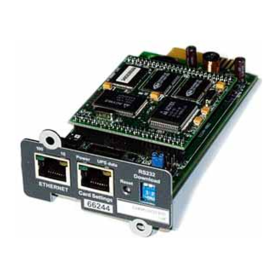
- Page 1 Network Management Cards User Manual Minislot 66244 Transverse 66074 Environment Sensor 66846 T H E U N I N T E R R U P T I B L E P O W E R P R O V I D E R...
-
Page 2: Table Of Contents
www.mgeups.com Network Management Cards User Manual Table of Contents MGE NETWORK SOLUTION____________________________________________________________4 _____________________________________________________________________4 NTRODUCTION 1.1.1 Connecting the UPS to the Network ________________________________________________4 The Network Management Card or Proxy: __________________________________________________4 1.1.2 Protecting the computers / servers _________________________________________________5 1.1.3 Monitoring the UPSs over the network ______________________________________________5 1.1.4 Connection ___________________________________________________________________6 (NMC) ________________________________6... - Page 3 www.mgeups.com Network Management Cards User Manual __________________________________________________________________30 ONFIGURATION 3.5.1 Network Settings _____________________________________________________________31 3.5.2 System _____________________________________________________________________33 3.5.3 Notified Applications ___________________________________________________________35 3.5.4 Central Shutdown Configuration__________________________________________________36 3.5.5 Access control _______________________________________________________________37 3.5.6 Time _______________________________________________________________________40 ____________________________________________________________________41 NVIRONMENT 3.6.1 Characteristics _______________________________________________________________41 3.6.2 Environment status ____________________________________________________________42 3.6.3 Environment Settings __________________________________________________________43 3.6.4 Log ________________________________________________________________________44...
-
Page 4: Mge Network Solution
www.mgeups.com Network Management Cards User Manual 1 MGE Network Solution 1.1 Introduction provides information on events concerning the supply of power to the computers connected to your computer network, carries out automatic shutdown of computer systems, monitors and controls all the UPSs connected to the network. As illustrated in the picture below, MGE Network Solution provides these 3 main functions: connecting the UPS to the Network, protecting the computers,... -
Page 5: Protecting The Computers / Servers
www.mgeups.com Network Management Cards User Manual makes this information available to the connected applications (Network Shutdown Modules, Web Browser, Network Management Systems, Enterprise Power Manager) Operation may be in standard secure mode (the default mode) or in SSL secure mode (Secure Socket Layer SSL). -
Page 6: Connection
NMC Minislot for UPS systems like the Evolution, EXtreme C, Pulsar EX RT, Pulsar/Comet DX series. NMC Transverse for UPS systems like the Galaxy 3000, Galaxy 5000, Galaxy PW, Pulsar and Comet EXtreme series. Other MGE UPS systems (3-phase Comet, Galaxy, EPS 6000) can be remotely managed using the Network Management Link... -
Page 7: Direct Sending Of E-Mail
www.mgeups.com Network Management Cards User Manual 1.4 Direct sending of E-mail When a UPS event occurs, the Network Management Card can directly notify up to 4 intranet or extranet addressees by e-mail (see Email Notification Email Message Settings). 1.5 Sending text messages (SMS) SMS messages can be sent by specific configuration of the e-mail function via the internet access providers making the e-mail / SMS transfer. -
Page 8: Technical Data
www.mgeups.com Network Management Cards User Manual 1.8 Technical data 1.8.1 Configuration The user can configure the card with one of the following means: Web browser Local serial link Telnet console BOOTP/DHCP Mupgrade 1.8.2 Administration Up to 50 workstations protected Up to 15 browsers connected at the same time E-mail sending configurable according to UPS alarms and transmission of a periodical report Measurement of temperature and humidity, adjustable thresholds, possibility of sending e-mails and shutting down the installation... -
Page 9: User Manual
www.mgeups.com Network Management Cards User Manual Recording of events and measurements in the card log Possibility of shutting down the installation in the event of a threshold being exceeded or on opening / closure of a dry contact Connection to the card with straight CAT5 RJ45 network cables (maximum card/sensor distance: 20 m) T H E U N I N T E R R U P T I B L E P O W E R... -
Page 10: Installation And Configuration
www.mgeups.com Network Management Cards User Manual 2 Installation and Configuration For the following sections, read the installation manual supplied with the card or available for download on the www.mgeups.com web site in the “Download area – embedded Software” section 2.1 Installation 2.1.1 Installing the card in the UPS 2.1.2 Connecting the card to the IT network 2.1.3 Understanding front panel signals... -
Page 11: Supervision / Administration Via A Web Browser
www.mgeups.com Network Management Cards User Manual 3 Supervision / Administration via a Web browser A JVM (Java Virtual Machine) is required to ensure correct display of information in HTML pages. On a computer equipped with a Web browser (Internet Explorer or Netscape recommended), enter the address initialised previously in the Installation chapter (e.g.: http://213.30.17.30.) The “UPS properties”... -
Page 12: Ups
www.mgeups.com Network Management Cards User Manual 3.2 UPS 3.2.1 “UPS properties” page This page gives instant access to the essential information about your UPS. This page is automatically refreshed every 10 seconds (by default). To change this value, go to the “System” page. 3.2.1.1 UPS zone: general information on the UPS. - Page 13 www.mgeups.com Network Management Cards User Manual • Battery operation • • Loss of communication with the UPS • • Battery fault • • Outlet powered – Flashing when an • (green outlet) on/off sequence is in progress • Outlet not powered or not protected •...
-
Page 14: On-Line Help
www.mgeups.com Network Management Cards User Manual 3.2.2 On-line help On-line contextual help in English is available at the top of each page by clicking on the Help link, which is always located on the top right corner. The Help page always opens a new window. T H E U N I N T E R R U P T I B L E P O W E R... -
Page 15: 3-Phase Display
www.mgeups.com Network Management Cards User Manual 3.2.3 3-Phase display Click 3-phase display to access to the detailed monitoring page This item is added to the menu for all single UPSs having a three-phase output. The link on the gauge symbols gives access to the measurement page related to the function. Function symbols are outlined in red when an alarm is present. -
Page 16: Ups Control
www.mgeups.com Network Management Cards User Manual 3.2.3.2 Battery measurements Remaining backup time estimted by the UPS Battery charge level Battery voltage Battery current – Negative when discharging Battery temp. – Internal temperature probe 3.2.3.3 By Pass measurements By Pass current By Pass voltagePhase / Phase 3.2.4 UPS Control Click on the “UPS Control”... - Page 17 www.mgeups.com Network Management Cards User Manual The main outlet has priority over the auxiliary outlets. Shutdown of the main outlet causes the auxiliary outlets to shut down. Auxiliary outlets can only be started if the main outlet is powered The Check column proposes six different commands, and a command is only actually started after clicking on 'Execute': “Safe power down”: a sequence to switch off output power is launched immediately.
-
Page 18: Ups Weekly Schedule Programming
www.mgeups.com Network Management Cards User Manual 3.2.5 UPS weekly schedule programming Click on the “Weekly schedule” section of the menu. If the UPS is not compatible with this function, a warning message is sent to the user. UPS configuration may also prevent the commands from being properly run. Read the UPS manual for more information. -
Page 19: Shutdown Parameters
www.mgeups.com Network Management Cards User Manual 3.2.6 Shutdown parameters Click on the “Shutdown parameters” section in the menu to see the list of parameters. Important note: For installations that do not use Network Shutdown Module (backup units, routers and other internetworking equipment, automated systems, etc.) or in the event of long backup periods, the card will send a command to the UPS to shut off end of the programmed Shutdown After time. - Page 20 www.mgeups.com Network Management Cards User Manual Restart after is the minimum shutdown time before restarting the UPS after a shutdown sequence. It is thus possible to limit repeated restarts that may be due to several successive utility failures. If the Battery is charged for and If Capacity exceeds are two extra conditions for minimum battery level and maximum recharge time to be reached before restarting the UPS after utility restoration For controlled outlets (group 1 or group 2 ), the page enables programming of operation time and level in backup mode to manage outlet load shedding in the event of electric power failure:...
-
Page 21: Viewing The Alarms
www.mgeups.com Network Management Cards User Manual 3.2.7 Viewing the alarms Click on the “Alarm table” section in the menu to view the list of current alarms. The table of managed alarms is included in the appendix. Note: The alarm number is not related to the SNMP trap number T H E U N I N T E R R U P T I B L E P O W E R... -
Page 22: Logs
www.mgeups.com Network Management Cards User Manual 3.3 Logs 3.3.1 Measurements Click on the “Measurements” section in the menu. The following measurements are saved and time-stamped: “Input voltage”: Value of the utility voltage supplying your UPS (average of 3 phases for UPS' equipped with a 3-phase input) “Input frequency”: Value of the utility frequency feeding your UPS “Output voltage”: Value of the output voltage of your UPS (average of the 3 phases for UPS’... - Page 23 www.mgeups.com Network Management Cards User Manual T H E U N I N T E R R U P T I B L E P O W E R P R O V I D E R Network Management Card Page –...
-
Page 24: Event Log
www.mgeups.com Network Management Cards User Manual 3.3.2 Event log Click in the “Event log” section of the menu. “Save Log” enables all values saved to be opened or saved in CSV format (compatible with Excel type spreadsheets). “Clear Log” enables deletion of all records. The administrator must enter his/her login / password to validate this action. -
Page 25: System Log
www.mgeups.com Network Management Cards User Manual 3.3.3 System log Click in the “System log” section in the menu. “Save” enables all values saved to be opened or saved in CSV format (compatible with Excel type spreadsheets). “Clear” enables deletion of all records. The administrator must enter his/her login / password to validate this action. -
Page 26: Notification
www.mgeups.com Network Management Cards User Manual 3.4 Notification 3.4.1 Email Notification The card offers the possibility of redirecting UPS alarms to an e-mail server. The format of these e-mails is compatible with mobile telephone transfer systems using text messages (SMS). Notified events: The left side of the page shows the events that can be notified. - Page 27 www.mgeups.com Network Management Cards User Manual Recipient List: On the right side of this page, up to four recipients can be configured to receive e-mails from the card. Each addressee has its own trigger events, selected from the left side of the page, for which an e-mail is sent. The card’s log indicates e-mail transmission errors.
-
Page 28: Email Message Settings
www.mgeups.com Network Management Cards User Manual 3.4.2 Email Message Settings This page enables customisation of the content of the messages received by recipients of e-mails sent by the card. Customisation is common to the four recipients that can be notified (see E-mail notification). - Page 29 www.mgeups.com Network Management Cards User Manual T H E U N I N T E R R U P T I B L E P O W E R P R O V I D E R Network Management Card Page –...
-
Page 30: Configuration
www.mgeups.com Network Management Cards User Manual 3.5 Configuration The parameters of this menu can only be modified after entering the “User Name” and “Password”. The following screen is proposed automatically: User Name and password by default are: MGEUPS Each field accepts up to 10 characters max. After entering the login and password, these identifiers remain active as long as the browser is open, so you only have to enter them once. -
Page 31: Network Settings
www.mgeups.com Network Management Cards User Manual 3.5.1 Network Settings Click on the “Network” section in the menu. This menu enables the administrator to configure the network parameters of the card and authorisation of the remote upgrade of the embedded system. IP address: The IP address of the card (e.g.: 172.17.23.205). - Page 32 www.mgeups.com Network Management Cards User Manual Mode of card operation with server: after any reboot, if this option is enabled, the card tries to recover the network parameters from the server for 10 sec. If no response is received from the server, the card boots with the last saved parameters from the previous start.
-
Page 33: System
www.mgeups.com Network Management Cards User Manual 3.5.2 System Click the “System” section in the menu. This menu enables the customisation of the information on the UPS properties Environment pages. UPS contact: This text field is limited to 32 characters. Enter the name of the person responsible for UPS administration at IT network level and/or electrical maintenance. - Page 34 www.mgeups.com Network Management Cards User Manual Environment log interval: [from 5 to 99999 sec ]. Temperature and humidity measurement save period. Default value = 300 sec. (only visible if the sensor is present). Environment refresh rate: [from 5 to 99999 sec]. “Environment status” page refresh rate. Default value = 60 sec.
-
Page 35: Notified Applications
www.mgeups.com Network Management Cards User Manual 3.5.3 Notified Applications Click the “Notified Application” section in the menu. Security: the administrator has to enter his login/password to view this information. This menu enables: The addition of the supervision stations receiving traps and configuration of the trap type. To list all the Notified Applications and the main parameters. -
Page 36: Central Shutdown Configuration
www.mgeups.com Network Management Cards User Manual Remove : Depending on the kind of application, the selected ones will definitively disappear from the table as SNMP applications, or they will disappear and automatically re-subscribe as the Network Shutdown Module application. Utility failure Test : Two alarms 'Utility failure' and 'Utility restored' spaced of 60 seconds will be sent to the applications selected, making sure that the applications can be reached over the network. -
Page 37: Access Control
www.mgeups.com Network Management Cards User Manual This page is used to define either the shutdown or the notification settings used by the Network Shutdown Modules that connect to Network Management Card. These settings are used by the Network Shutdown Modules if they are in centralized-configuration mode or if their configuration is not valid. Shutdown After (time before shutdown) This is the time in seconds that the system waits following failure of AC power before initiating the system-shutdown procedure. - Page 38 www.mgeups.com Network Management Cards User Manual Enter New Manager Login: Text field limited to 10 characters. Enables secure access and modification of pages. Default value “MGEUPS”. Enter New Password: Text field limited to 10 characters. Enables secure access to the sections of the Configuration menu.
- Page 39 www.mgeups.com Network Management Cards User Manual Change Trap Port Number: Numeric field limited to 65534. Enables forwarding of traps sent by the card to a port other than the port usually used for SNMP. Default value 162. SSL Activation: When selected, access to Web interface is made in secure mode (https). Telnet access is disabled and the card is accessible in SSH.
-
Page 40: Time
www.mgeups.com Network Management Cards User Manual 3.5.6 Time Click the “Time” section in the menu. This menu enables initialisation of the date and time of the card in three different ways. Synchronise manually: Enables initialisation of the date and time of the card, with the values entered in the Date and Time fields. -
Page 41: Environment
www.mgeups.com Network Management Cards User Manual The card uses the NTP protocol (UDP 123 port) and the firewall must be set accordingly, no error message is generated if the time server contact fails Daylight Saving Time: Enables corrections due to summer / winter time changes, this option must be supported by the NTP server. -
Page 42: Environment Status
www.mgeups.com Network Management Cards User Manual Connection to the Network Management Card by CAT5 straight RJ45 network cables (maximum card/sensor distance: 20m) 3.6.2 Environment status For both measurements, a graduated gauge proposes the following functions: The cursor indicates the current value. Two red zones to the left and right represent the high and low thresholds that can be set on the Environment Settings... -
Page 43: Environment Settings
www.mgeups.com Network Management Cards User Manual 3.6.3 Environment Settings The environment sensor measures temperature, humidity and gives the status of the 2 contacts (used for door, alarms or generator unit). The temperature and humidity thresholds can be adjusted and can trigger notification and correct shutdown of the protected system. -
Page 44: Log
www.mgeups.com Network Management Cards User Manual Hysteresis must be set to prevent multiple notifications if humidity fluctuates around a threshold. Default value is 5%. (Advanced parameters) The high alarm cannot be reactivated while humidity remains above the High threshold – Hysteresis value. The low alarm cannot be reactivated while humidity remains below Low threshold + hysteresis value. -
Page 45: Servers Protection
www.mgeups.com Network Management Cards User Manual 4 Servers protection 4.1 Set-up of the shutdown parameters The Network Shutdown Module, on protected server boot, subscribes itself automatically to Notified Applications list and sends its essential data: IP address or name of the server on which it is installed, to be notified by the card of any power events Time required to shutdown the server (Shutdown Duration, configurable in the Shutdown Module “set-up”... -
Page 46: Specific Set-Up For Long Autonomy Installation (> 30 Mn)
www.mgeups.com Network Management Cards User Manual 4.1.1.3 Shutdown when backup time is less than When the Network Management Card detects that the percentage of backup time remaining is less than the value set, the shutdown sequence is started. 4.1.1.4 Shutdown duration Duration required for the systems protected by the Shutdown Modules to shut down (in seconds). - Page 47 www.mgeups.com Network Management Cards User Manual 4.1.4.1 Load shedding or sequential shutdown It is possible to optimise backup time by shutting down non-priority equipment or sequencing the shutdown of several devices. Two shutdown criteria are possible: Shutdown of outlets after a set battery back-up time (ShutOff Delay) Shutdown of outlets at a given battery discharge level (ShutOff Level) It is possible to specify values for both criteria.
-
Page 48: The Different Server And Ups Shutdown Sequences
www.mgeups.com Network Management Cards User Manual The different server and UPS shutdown sequences 4.2.1 Extended power outage, shutdown initiated by the Shutdown Timer During battery backup time, the Shutdown Timer of the Network Management Card is reached: after a user- defined backup time period, the shutdown of all servers is initiated, followed by the UPS shutdown (depending on its configuration). - Page 49 www.mgeups.com Network Management Cards User Manual 4.2.1.3 Programmable outlet 2 Shuts down after Shutoff Delay 2 after having stopped the servers Restarts when utility power is restored by applying Restart Delay 2 Trap 29 ShutoffDelay 2 Restart Trap 31 Shutdown Duration.2 Trap 32 UM-Client...
-
Page 50: Extended Power Outage, Shutdown Initiated By The "Low Battery Power" Message
www.mgeups.com Network Management Cards User Manual 4.2.2 Extended power outage, shutdown initiated by the “Low battery power” message When the ”Low battery power” message is displayed, the UPS is shut off after taking into account the shutdown duration of the servers. “Low battery power”: The message appears if either of the two following criteria is checked: - Low Battery Level - Minimum remaining backup time (Low Battery Delay) - Page 51 www.mgeups.com Network Management Cards User Manual UM-Client Shutdow Rebo Outlet 2 T H E U N I N T E R R U P T I B L E P O W E R P R O V I D E R Network Management Card Page –...
-
Page 52: Extended Power Outage, Shutdown Initiated By The Shutdown Timer, But Utility Restoration Before The End Of The Shutdown Duration
www.mgeups.com Network Management Cards User Manual 4.2.3 Extended power outage, shutdown initiated by the Shutdown Timer, but utility restoration before the end of the Shutdown Duration If utility power is restored before the end of the Shutdown Duration, the UPS is shut off after the Shutdown Duration for a period equal to the forced reboot time delay 4.2.3.1 Main UPS outlet Utility... - Page 53 www.mgeups.com Network Management Cards User Manual 4.2.3.3 Programmable outlet 2 Trap 29 ShutoffTimer.2 Restart Delay.2 Trap 31 Shutdow Trap 32 UM-Client Shutdow Rebo Outlet 2 T H E U N I N T E R R U P T I B L E P O W E R P R O V I D E R Network Management Card...
-
Page 54: Off/On Command
www.mgeups.com Network Management Cards User Manual 4.2.4 Off/On command Off/On command is sent from the “UPS control” page After a power on, controls are disabled during 120 secondes to allow the server to reboot. 4.2.4.1 Main outlet Utility Off command with a On command with a shutdown delay = 2 minutes... - Page 55 www.mgeups.com Network Management Cards User Manual 4.2.4.3 Programmable outlet 2 Trap 29 ShutoffTimer.2 Restart Delay.2 Trap 31 Shutdow Trap 32 UM-Client Shutdow Rebo Outlet 2 T H E U N I N T E R R U P T I B L E P O W E R P R O V I D E R Network Management Card...
-
Page 56: Configuring A Set Of Cards With Mupgrade
(MGEUPS by default), and then press “Enter”. The card will disconnect itself after 3 minutes of inactivity. The menu is in English only. +=========================================================================== [ MGE UPS SYSTEMS SNMP/Web agent Configuration menu ] +=========================================================================== Enter Password: ****** +=========================================================================== [ MGE UPS SYSTEMS SNMP/Web agent Configuration menu ] +=========================================================================== 1. -
Page 57: Choice 1: Snmp Agent Configuration Menu
www.mgeups.com Network Management Cards User Manual Please Enter Your Choice => 6.1.1 Choice 1: SNMP agent configuration menu The blue lines are those displayed on screen. +============================================================================+ [ Agent Configuration Menu ] +============================================================================+ SNMP/Web Agent Version : GA (SN 49DC40116) Indicates the version level of the software and the serial number of the card. -
Page 58: Choice 2: Ups Parameters
www.mgeups.com Network Management Cards User Manual Text field limited to 10 characters. Enables secure access to the sections of the Configuration menu. Default value “MGEUPS”. b. BOOTP/DHCP Enabled : Enabled Authorises the configuration of network parameters with your BootP/DHCP as a startup mode (choose enable). Card operating mode with the server: after all reboots, the card (if this option is enabled), attempts to recover the network parameters from the server for 10 seconds. -
Page 59: Choice 4: Restore Default Configuration
www.mgeups.com Network Management Cards User Manual Please Enter Your Choice => This menu enables configuration of access to the four supervision stations (identified by the IP address) with read/write community names different to those already defined in the card “1” menu. First enter the figure corresponding to the command to be carried out, then the number of the target input. -
Page 60: Configuration Via Telnet
www.mgeups.com Network Management Cards User Manual 6.2 Configuration via Telnet You can access the configuration menu (see “configuration in local mode” section) from a station equipped with the Telnet protocol. As soon as the card is accessible on the network, enter the command: telnet <... - Page 61 www.mgeups.com Network Management Cards User Manual Select SSH : and Clic on « Open » to start connection T H E U N I N T E R R U P T I B L E P O W E R P R O V I D E R Network Management Card Page...
-
Page 62: Maintenance
www.mgeups.com Network Management Cards User Manual 7 Maintenance 7.1 Software upgrade 7.1.1 Card firmware upgrade using Mupgrade (Windows) This feature is particularly useful to upgrade a large UPS installed base in one operation. Read the relevant documentation available for download on the www.mgeups.com web site, in the “Download... -
Page 63: Appendices
www.mgeups.com Network Management Cards User Manual 8 Appendices 8.1 Tables of alarms and events 8.1.1 Alarm table English French Battery Fault Défaut batterie Output On Battery Sortie alimentée par batterie Low Battery Fin d’autonomie UPS Over Temperature Défaut température Output not protected Sortie non protégée UPS Overload Surcharge onduleur... - Page 64 www.mgeups.com Network Management Cards User Manual UPS battery exiting from minimum Fin batterie en charge minimum condition Output on battery Sortie alimentée par batterie Return on UPS Sortie sur onduleur Output on Bypass Sortie sur Bypass Bypass : Return on UPS Sortie sur onduleur UPS bypass unavailable Bypass indisponible...
- Page 65 www.mgeups.com Network Management Cards User Manual Bypass switch (Q4S) closed Interrupteur bypass (Q4S) fermé Battery switch (QF1) closed Disjoncteur batterie QF1 fermé Battery switch (QF1) open Disjoncteur batterie QF1 ouvert Manual bypass switch (Q3BP) Interrupteur bypass manual (Q3BP) fermé closed Manual bypass switch (Q3BP) open Interrupteur bypass manual (Q3BP) ouvert Output switch (Q5N) closed...
-
Page 66: System Alarm Table
www.mgeups.com Network Management Cards User Manual 8.1.3 System alarm table English French Cold boot Démarrage de la carte Warm boot Réinitialisation de la carte Network link up Carte connectée au réseau Network link down Carte déconnectée du réseau Agent Card Restart Redémarrage de la carte Parameters reset to default Paramètres par défaut reprogrammés... -
Page 67: Glossary
www.mgeups.com Network Management Cards User Manual 8.2 Glossary Bootp: Protocol based on UDP used to allocate an IP address corresponding to an Ethernet card during the startup phase. Defined by the RCF 951 Community name: Access key to access SNMP agent information DHCP Dynamic Host Configuration Protocol This IETF protocol enables remote, automatic, self-configuration of the IP addresses of a workstation. - Page 68 www.mgeups.com Network Management Cards User Manual Communication cards to supervise UPS and communicate with Network Shutdown Module to insure power protection on servers NETWORK MANAGEMENT PROXY Communication software installed on a PC connected to the UPS to supervise it and communicate with Network Shutdown Module to insure power protection on servers NMS NETWORK MANAGEMENT STATION (SNMP) The dedicated PC or workstation is used on the company’s networks to administrate all devices connected to...
- Page 69 www.mgeups.com Network Management Cards User Manual Internet protocol used for terminal emulation, i.e. enabling a computer to connect with a server as if it was a simple terminal locally connected to this server. Trap (SNMP) This term describes an event that affects an MIB variable. Traps are sent to the manager, which is programmed to perform specific tasks upon reception of the traps.
Need help?
Do you have a question about the minislot 66244 and is the answer not in the manual?
Questions and answers