Advertisement
TECHNICAL MANU
TECHNICAL MANU AL
TECHNICAL MANU
TECHNICAL MANU
TECHNICAL MANU
•
Refer to Service Manual RS6200007 for installation, operation, and troubleshooting information.
•
All safety information must be followed as provided in the Service Manual.
•
Refer to the appropriate Parts Catalog for part number information.
•
Models listed on page 2.
This manual is to be used by qualified, professionally trained HVAC technicians only. Goodman
does not assume any responsibility for property damage or personal injury due to improper
service procedures or services performed by an unqualified person.
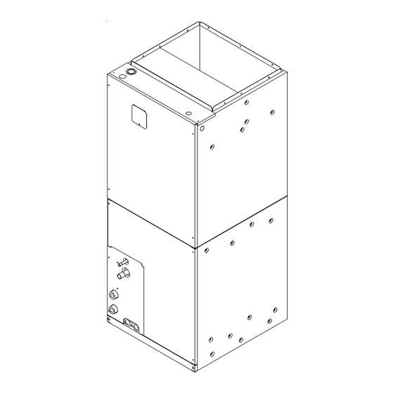
MBVC Blowers
Copyright © 2009 Goodman Manufacturing Company,
AL
AL
AL
AL
September 2009
L.P.
RT6223003
Advertisement
Table of Contents

Related Manuals for Goodman MBVC RT6223003


Summary of Contents for Goodman MBVC RT6223003
- Page 1 TECHNICAL MANU TECHNICAL MANU AL TECHNICAL MANU TECHNICAL MANU TECHNICAL MANU • Refer to Service Manual RS6200007 for installation, operation, and troubleshooting information. • All safety information must be followed as provided in the Service Manual. • Refer to the appropriate Parts Catalog for part number information. •...
-
Page 2: Product Identification
PRODUCT IDENTIFICATION The model number is used for positive identification of component parts used in manufacturing. Please use this number when requesting service or parts information. DESIGN SERIES: MB: Modular Blower COMMUNICATION FEATURE: C: 4-wire Communication Ready MOTOR TYPE: V: Variable Speed... - Page 3 ECM motors on the MBVC models. EATURES This modular blower is a part of the ComfortNet™ family of products. It may be installed as part of a “legacy” system using a standard 24 VAC thermostat. However, with the CTK01AA ComfortNet™...
- Page 4 MBVC1200 10X8 MBVC1600 10X8 MBVC2000 11X10 Minimum Circuit Ampacity (MCA) and Maximum Overcurrent Protection (MOP) for blower without supplemental heat installed. Refer to unit nameplate for MCA and MOP with approved accessory heaters installed. 5 1/8 MBVC1200/1600/2000 Blower Motor (HP)
- Page 5 MBVC BLOWER SPECIFICATIONS BLOWER OPENING DIMENSIONS HKR HEATER DATA BLOWER NO HEAT KIT MBVC 1200AA-1AA 1600AA-1AA 2000AA-1AA ^ = Circuit 1: Single Phase for Air Handler Motor Circuit 2: 3-Phase for HKR3 Heater Kits X = Allowable combinations ~ = Restricted combinations...
- Page 6 1200 1340 Locate the blower speed selection DIP switches on the integrated control module. Select the desired “cooling” speed tap by positioning switches 1 and 2 appropriately. Select the desired “adjust” tap by positioning switches 3 and 4 appropriately. Refer to the following figure for switch positions and their corresponding taps.
-
Page 7: Wiring Diagrams
(Two-Stage AC) Typical Two-Stage Cooling with Two-Stage Heating W1 W2 Y1 Remote Condensing Unit (Two-Stage HP) THERMOSTATS Typical Two-Stage Cool, Two-Stage Heat Thermostat Modular Blower Integrated Control Module DEHUM Dehumidistat [Optional] Typical Two-Stage Cool, Two-Stage Heat Heat Pump Thermostat Modular Blower... - Page 8 ONE (1) ELEMENT ROWS NOTE: WHEN INSTALLING HEATER KIT, ENSURE SPEED TAP DOES NOT EXCEED MINIMUM BLOWER SPEED (MBS) SPECIFIED FOR THE AIRHANDLER/HEATER KIT COMBINATION ON THIS UNIT'S S&R PLATE. AFTER INSTALLING OPTIONAL HEAT KIT, MARK AN "X" IN THE MARK ACCORDING TO NUMBER OF HEATER ELEMENT ROW S INSTALLED.
Need help?
Do you have a question about the MBVC RT6223003 and is the answer not in the manual?
Questions and answers