
Related Manuals for Goldstar MONOCHROME MONITOR MBM-2105GIA

Summary of Contents for Goldstar MONOCHROME MONITOR MBM-2105GIA
-
Page 1: Service Manual
GolclStar MONOCHROME MONITOR SERVICE MANUAL WTI O N BEFORE SERVICING THE CHASSIS, READ THE “SAFETY PREtXJTK)NS”, IN THIS MANUAL MODEL: MBM-2105GIA (MC-3 CHA=W B GoldStar... -
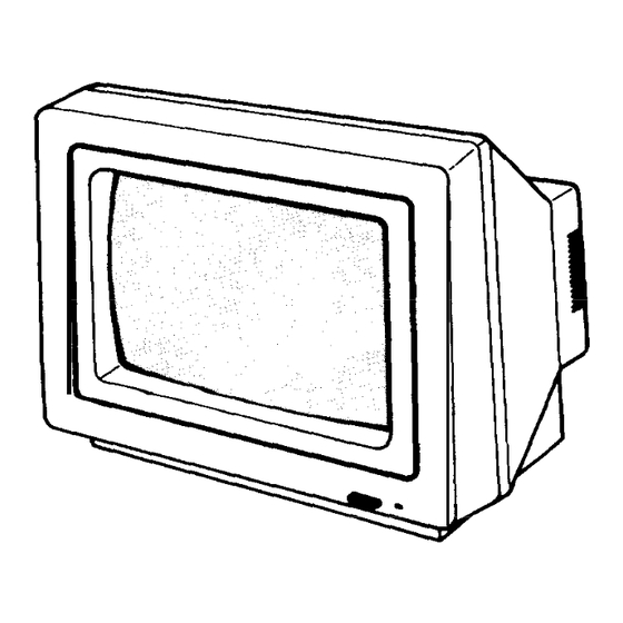
Page 2: Controls Location
2000 display characters in a 8 x 8 dot format. 18 MHz bandwidth, medium class, composite signal input. This monitor is compatible with a variety of home and personal computers CONTROLS LOCATION The MBM-2105GIA monochrome monitor uses a RCA jack connector. The input signal is input through the RCA jack connector. -
Page 3: Video Amplifier
VIDEO AMPLIFIER The Fig. 3 details the cascade video amplifier. Video amplification is provided by the TR303 and TR304. TR303 and TR304 are connected in a cascade configuration. TR303 common emitter and TR304 operates in the common base configuration. This minimized the miller effect input capacitance and the difining breakdown parameter for TR303 which becomes BVCBO as opposed to BVCEO. - Page 4 Frame-Synchro Figure 4, BLOCK DIAGRAM OF THE TEA 2037A 3. COMPOSITE VIDEO INPUT AND HORIZONTAL/ VERTICAL DEFLECTION 3-l VIDEO INPUT (PIN 15) The detection level for negative sync pulse at the sync separation input (pin 15) is set at 1.6V. When the voltage at emitter of the Transistor (pin 15) is above 1.6V, the transistor is cut off.
-
Page 5: Centering Adjustment
REGULATED B + ADJUSTMENT (VRSOl) Connect high impedance voltmeter between TR901 emitter and ground rotate the B + adjustment control (VR901) to obtain a reading of 12.0 2 O.lV. FOCUS (VR704) Adjust the focus control (VR704) for best overall focus of the test pattern (marked with the symbol “%“). - Page 6 0901-0904 lN5392GP.4 NOTES: 1. RESISTORS ARE SHOWN IN OHMS 2. CAPACITORS ARE SHOWN 3. All RESISTORS ARE f 5% CONTRAST VR301 5008 1 2 . 7 TR902 C908 Kltl959-O/Y c905 2200/2! F901 20.6 T750mA 25OV IUL/CSAI 1315mA25OV NDE/SEtlKOI K = 1.000 M = 1.000.000 IN UF OTHERWISE NOTED P : cc Ir TOLERANCE UNLESS OTHERWISE NOTED...
- Page 7 DIAGRAM 3OvI+ 01G.h R719 R7OI c 7 1 7 L.wv OwLI/ loowl tl.OUl c708 L.7/50 ‘711 & \I-Ln 4 IMPORTANT AVIS SUR LA SkURlTi. b TES SPECIAL LA m SYMBOLE MARQUE DE CE DIAGRAMME SCHEIIATIQUE COMPREND DIIIPORTANTES FIRE AND CARACTkRISTIQUES SPkIALES CON$UES P O U R PROTiGER IllAL T H A T D~NCENDIE...
-
Page 8: Troubleshooting Guide
TROUBLESHOOTING Y E S , C H E C K C R T (GZ) V O L T A G E 4 5 0 V 2 C H E C K C R T ( H E A T E R ) V O L T A G E 12V Y E S A B O V E 55V C H E C K C R T CATHOD... -
Page 9: Printed Circuit Board
PRINTED CIRCUIT BOARD 1. MAIN PCB ASSY PIN: 1 lo-BOW ASSY PIN: ilO-B72A GSEP-2112 BLACK... -
Page 10: Main Pcb (Solder Side)
3. MAIN PCB (SOLDER SIDE) 4. LINE FILTER PCB (SOLDER SIDE) Lsol... -
Page 11: Exploded View
EXPLODED VIEW *Outer Cabinet not used on 6300T Models. REPLACEMENT PARTS LIST (MECHANICAL PARTS) , 1ILr.I w ___ .- 1 COVER ASSY. B& 3X3-A02A 407-622A , I-LAIE., “x-t WNR ruvvcn, 407.696A 303.924A 1 C O V E R , C R T BOARD 303.928A [ COVER, PCB SHIELD CASE 1... -
Page 12: Replacement Parts List
CAUTION: Components identified by the A symbols in the PARTS LIST and on the SCHEMATIC DIAGRAM have special characteristics important to safety. Do not degrade the safety of the set through improper servicing. ABBREVIATIONS: Capacitors ..CC: Ceramic (TC), CE: Chemical, CK: Ceramic (Hi-K), Resistors . - Page 13 DESCRIPTION REF. NO. PART NO. CE. 2 2uF 160V C608 CE. 1OOuF 16V c701 CO, 0 1uF 1OOV C702 CE. 1 OuF 25V c 703 CO, 0 0022uF c704 PP 0 0022uF 200V c705 CO, 0 0022uF C 706 CQ. 0 015uF 1OOV c707 CE, 4 7uF 25V...
Need help?
Do you have a question about the MONOCHROME MONITOR MBM-2105GIA and is the answer not in the manual?
Questions and answers