
Related Manuals for GMC Gasoline V6 90 Degree


Summary of Contents for GMC Gasoline V6 90 Degree
- Page 1 Application Manual Gasoline 4.3L V6 90 Degree 2001 Model Year General Motors Powertrain Group...
- Page 2 ENGINE APPLICATION MANUAL GM Powertrain Gasoline 4.3L V6 90 Degree Revised: 08/15/2000 ENGINE APPLICATION MANUAL Gasoline 4.3L V6 90 Degree Engines RPO : L35 Model Year: 2001 General Motors Powertrain Group 895 Joslyn Ave MC: 480-710-225 Pontiac MI 48340 Contact:Luis Nespolo - (248) 857-1558...
-
Page 3: Introduction
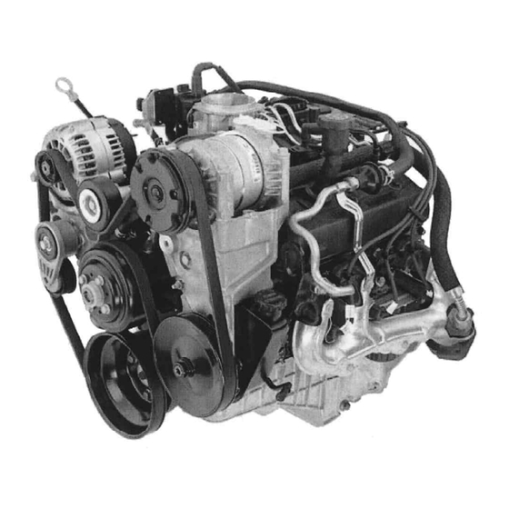
The more distinctive common features of this family of engines are: -Optimized Intake Manifold -Stiff Oil Sump -High reliability and durability -OBDII compliant File: c:\data\manuales\v6-truck\am43v6#3.doc Contact:Luis Nespolo - (248) 857-1558 L35 Isometric View Figure: 2.1-I GM Powertrain Revised: 08/15/2000 Printed: 8/15/00... -
Page 4: Product Specification Summary
Sequential Central Sequential Central Port Injection Port Injection 158@ 4600 rpm 158@ 4600 rpm Symmetrical Runner Symmetrical Runner Aluminum Aluminum Composite Composite GM Powertrain Revised: 08/15/2000 UNITS Lb. ft in hg Piezometer in hg Piezometer Degree C Degree cc.cm Gr/sec... - Page 5 Forged-SAE 1141 Forged-SAE 1141 154.9 154.9 Aluminum Tin Aluminum Tin Silicon Alloy Silicon Alloy 1.68:1 1.68:1 Strutless Strutless Flat Top Flat Top Eutectic Cast Eutectic Cast Aluminum Alloy Aluminum Alloy GM Powertrain Revised: 08/15/2000 UNITS Degree Cam Turned Printed: 8/15/00...
- Page 6 Silicon Alloy Silicon Alloy Ring Inertia Ring Inertia Negative Closed Negative Closed (Vacuum created from (Vacuum created from Intake Manifold) Intake Manifold) GM Powertrain Revised: 08/15/2000 UNITS Crk Degree Crk Degree Crk Degree Crk Degree Newtons Newtons/mm Rubber Mounted Printed: 8/15/00...
- Page 7 425 +/- 9 285 +/- 9 285 +/- 9 Delphi Delphi 44MM -G-Rotor 44MM –G-Rotor 6-12 6-12 Delphi Delphi Full Full Recirculation Recirculation Nylon 66 Nylon 66 GM Powertrain Revised: 08/15/2000 UNITS @ 2000 RPM @ Idle Gram/Sec Gram/Sec Volts Printed: 8/15/00...
-
Page 8: Fuel Requirements
Delphi Cartridge Cartridge Delphi Delphi Centrifugal Centrifugal 76.5 76.5 Ball/Roller Ball/Roller Cast iron Cast iron Cast iron Cast iron External External Deaeration Tank Bypass Bypass 1.25 1.25 GM Powertrain Revised: 08/15/2000 UNITS Octane = (R+M)/2 GPM @ 4600 Printed: 8/15/00... -
Page 9: Performance
246.1 99.1 260.2 254.3 120.3 262.5 258.2 143.4 269.1 257.9 166.4 272.7 254.4 188.2 274.1 247.1 206.2 270.2 233.0 217.6 259.5 220.8 252.0 216.3 221.6 242.3 194.2 216.0 218.0 GM Powertrain Revised: 08/15/2000 Industrial Notes Applications Torque Lbs.-ft Printed: 8/15/00... - Page 10 ENGINE APPLICATION MANUAL Gasoline 4.3L V6 90 Degree File: c:\data\manuales\v6-truck\am43v6#3.doc Contact:Luis Nespolo - (248) 857-1558 L35 Main Views L35 Front View L35 Rear View GM Powertrain Revised: 08/15/2000 Printed: 8/15/00...
- Page 11 ENGINE APPLICATION MANUAL Gasoline 4.3L V6 90 Degree File: c:\data\manuales\v6-truck\am43v6#3.doc Contact:Luis Nespolo - (248) 857-1558 L35 RH Side View L35 LH Side View GM Powertrain Revised: 08/15/2000 Printed: 8/15/00...
-
Page 12: Configuration As Shipped
File: c:\data\manuales\v6-truck\am43v6#3.doc Contact:Luis Nespolo - (248) 857-1558 Crankshaft sensor E.G.R. system Engine oil Exhaust manifold(s) Engine Fuel system Coolant temperature sensor/switch Oil pressure sensor/switch Transmission alignment dowels Flywheel and or Flexplate Crankcase ventilation system GM Powertrain Revised: 08/15/2000 Printed: 8/15/00... -
Page 13: Engine Option Description
Traction Control Right Hand Drive Brazil Equipment Venezuela Equipment Mexican Equipment G-Van Pull Ahead GM Powertrain Revised: 08/15/2000 Notes Tier 1 (-K18 on CK Manuals) (+K18 on CK / -K18 on M/L) (-K18 on ML) (-K18 on CK & P) (Export for ML &... -
Page 14: Engine Broadcast Codes & Part Numbers
Marine (Merc) 2Bbl w/o Dist. —- Marine 4Bbl w/ Dist. —- Marine 4Bbl w/o Dist. —- Indust 2Bbl Gaseous - Bucks Irrigation —- Indust 2Bbl Gas - Williams Powertrain L35+M50+S5I (Brazil) L35+M30+S5I (Brazil) GM Powertrain Revised: 08/15/2000 Description Printed: 8/15/00... -
Page 15: Gmpt System Interfaces
3.1.1- I. 3.1.1.1 Automatic Transmission The 4.3L V6 engine could be mated to either: the GM Automatic Transmission Hydra Matic 4L60E or the GM Automatic Transmission Hydra Matic 4L80E Figure 3.2.1-I to 3.2.1-XVIII shows the PCM Engine to Automatic Transmission Mechanization Diagram. - Page 16 ENGINE APPLICATION MANUAL Gasoline 4.3L V6 90 Degree The following table shows the different Transmissions and Components coupled to the L35 engine and GM platforms. Transmission ( UPC: 7 ) Auto 4L80E MT1 Bolt/Screw/Stud Auto 4L60E M30 Brace Bolt/Screw/Stud Manual 5-Speed MW3...
-
Page 17: Engine Interface To Pcm ( Vehicular And Marine/Industrial Application)
This pressure is determined by a table that is based on vehicle speed and Throttle position. Garage Shift quality (shifting from Park or Neutral to Drive or Reverse when the vehicle is stationary) is also controlled by torque signal pressure. File: c:\data\manuales\v6-truck\am43v6#3.doc Contact:Luis Nespolo - (248) 857-1558 GM Powertrain Revised: 08/15/2000 Printed: 8/15/00... -
Page 18: Tcc Control Algorithm
4WD Lo Switch (If Applicable) Diagnostic Enable Cruise Control Inputs Tow/Haul Input Switch 3.1.4.2 Output to the Vehicle: Data link Connector MIL “Service Engine Soon” Lamp “Service Throttle Soon” (STS) Lamp File: c:\data\manuales\v6-truck\am43v6#3.doc Contact:Luis Nespolo - (248) 857-1558 GM Powertrain Revised: 08/15/2000 Printed: 8/15/00... -
Page 19: Pcm Pin Out And Pin In - Truck Applications
See Figure 3.1.5 - I Powertrain Control Module Diagram to reference the following pin out and pin in connector information Figure : 3.1.5a - I PCM Pin Out /In Connector C1 File: c:\data\manuales\v6-truck\am43v6#3.doc Contact:Luis Nespolo - (248) 857-1558 GM Powertrain Revised: 08/15/2000 Printed: 8/15/00... - Page 20 ENGINE APPLICATION MANUAL Gasoline 4.3L V6 90 Degree Figure : 3.1.5a -II PCM Pin Out /In Connector C2 File: c:\data\manuales\v6-truck\am43v6#3.doc Contact:Luis Nespolo - (248) 857-1558 GM Powertrain Revised: 08/15/2000 Printed: 8/15/00...
- Page 21 ENGINE APPLICATION MANUAL Gasoline 4.3L V6 90 Degree The following table shows the different PCM ASM and Components coupled to the L35 engine per GM platforms. ( 12 F ) Module ASM Housing Extension Bracket Bolt/Screw/Nut Sensors ( 12 F )
-
Page 22: Pcm Pin Out And Pin In - Marine And Industrial Applications
ESTF J2-14 ESTD J2-15 ESTB_BYP* J2-16 J2-17 DEPSPWR J2-18 DEPSLO J2-19 J2-20 OILPRESS J2-21 J2-22 O2BHI J2-23 J2-24 CANHI J2-25 VSSVF J2-26 VSS_AN/FTEMP J2-27 TACDATA1 J2-28 ESTG J2-29 ESTE J2-30 ESTC J2-31 ESTA J2-32 GM Powertrain Revised: 08/15/2000 Printed: 8/15/00... - Page 23 ENGINE APPLICATION MANUAL Gasoline 4.3L V6 90 Degree File: c:\data\manuales\v6-truck\am43v6#3.doc Contact:Luis Nespolo - (248) 857-1558 GM Powertrain Revised: 08/15/2000 Printed: 8/15/00...
-
Page 24: Engine Interface To Exhaust
Maximum allowable leakage in each zone is 2 liters/minute at 15 kPa. File: c:\data\manuales\v6-truck\am43v6#3.doc Contact:Luis Nespolo - (248) 857-1558 Cylinder head / exhaust manifold interface to control oxygen sensor Control oxygen sensor to converter Converter to 12 inches downstream of the diagnostic oxygen sensor GM Powertrain Revised: 08/15/2000 Printed: 8/15/00... - Page 25 ENGINE APPLICATION MANUAL Gasoline 4.3L V6 90 Degree The following table shows the different Exhaust Assemblies and Components coupled to the L35 engine per GM platforms. Exhaust ( 8 C ) Manifold ASM Pipe ASM Exhaust Manifold Seal Manifold Gasket...
-
Page 26: Back Pressure
3.1.6.5 Secondary Air GMPT will indicate the needs for secondary air recirculation. The following table shows the different Secondary Air and EGR Assemblies and Components coupled to the L35 engine per GM platforms. Engine Secondary Air ( 6T ) Pump Air Inj ASM... -
Page 27: Engine Interface To Cruise Control
Figure 3.2.1-I to 3.2.1-XVIII shows the PCM Engine to Vehicle Mechanization Diagram with this interface. The following table shows the different Fuel Lines, Fuel Tank and Evaporative Assemblies and Components coupled to the L35 engine per GM platforms. Fuel Evaporative... -
Page 28: Accessory Drive System
Cooling Fan assembly is not part of the engine scope or extent of supply. Cooling fan is designed, dimensioned and released by the GM - HVAC engineering group taking in consideration the Heat Rejection (indicated in the paragraph 3.4.5) needed to evacuate from the engine through the radiator assembly. - Page 29 11516283 10244168 10244168 10244168 10242827 10242827 10242827 10224557 10224557 10224557 10237271 11516284 WE08 UT06 OAKQ 10236997 10236997 10236997 GM Powertrain Revised: 08/15/2000 MY-2001 MY-2001 M/L -Van S/T Truck 26057292 26058060 10085755 10085755 10236998 26057780 26057733 26057936 26063303 26042259 26055306 26055306...
-
Page 30: Interfaces With Vehicle Subsystems
Spark Plug See Table 3.1.11-I Accessory Drive Brackets Components Combination for Generator usage information. The following table shows the different Harnesses and components used with the L35 engine per GM platforms. Electrical ( 12 H ) Harness ASM Harness Extension... - Page 31 Brake, ABS Switch, Serial Data Link I/P Cluster & Cruise Module Oxygen Sensors Idle Air Controller & Knock Sensor Fuel System and Optional ETC Engine Ignition System Engine Crank & Cam Sensors HVAC Power Distribution Note & references GM Powertrain Revised: 08/15/2000 Printed: 8/15/00...
- Page 32 ENGINE APPLICATION MANUAL Gasoline 4.3L V6 90 Degree Figure 3.2.1a - I - P/Truck - Mechanization Diagram – Cooling, MAP, TPS and OIL Sensors File: c:\data\manuales\v6-truck\am43v6#3.doc Contact:Luis Nespolo - (248) 857-1558 GM Powertrain Revised: 08/15/2000 Printed: 8/15/00...
- Page 33 ENGINE APPLICATION MANUAL Gasoline 4.3L V6 90 Degree Figure 3.2.1a – II – P/Truck - Mechanization Diagram – EGR, Purge & Vent Solenoid Fuel Canister File: c:\data\manuales\v6-truck\am43v6#3.doc Contact:Luis Nespolo - (248) 857-1558 GM Powertrain Revised: 08/15/2000 Printed: 8/15/00...
- Page 34 ENGINE APPLICATION MANUAL Gasoline 4.3L V6 90 Degree Figure 3.2.1a - III - P/Truck - Mechanization Diagram-VSS (TISS & TOSS), Air Pump & Solenoid Relay File: c:\data\manuales\v6-truck\am43v6#3.doc Contact:Luis Nespolo - (248) 857-1558 GM Powertrain Revised: 08/15/2000 Printed: 8/15/00...
- Page 35 ENGINE APPLICATION MANUAL Gasoline 4.3L V6 90 Degree Figure 3.2.1a - IV - P/Truck - Mechanization Diagram – Engine to Transmission (Auto & Manual) File: c:\data\manuales\v6-truck\am43v6#3.doc Contact:Luis Nespolo - (248) 857-1558 GM Powertrain Revised: 08/15/2000 Printed: 8/15/00...
- Page 36 ENGINE APPLICATION MANUAL Gasoline 4.3L V6 90 Degree Figure 3.2.1a - V - P/Truck - Mechanization Diagram – Engine Injectors File: c:\data\manuales\v6-truck\am43v6#3.doc Contact:Luis Nespolo - (248) 857-1558 GM Powertrain Revised: 08/15/2000 Printed: 8/15/00...
- Page 37 ENGINE APPLICATION MANUAL Gasoline 4.3L V6 90 Degree Figure 3.2.1a - VI - P/Truck - Mechanization Diagram – TCC Switch & Cruise Control File: c:\data\manuales\v6-truck\am43v6#3.doc Contact:Luis Nespolo - (248) 857-1558 GM Powertrain Revised: 08/15/2000 Printed: 8/15/00...
- Page 38 ENGINE APPLICATION MANUAL Gasoline 4.3L V6 90 Degree Figure 3.2.1a - VII - P/Truck - Mechanization Diagram – Starter, Alternator & IP Gages File: c:\data\manuales\v6-truck\am43v6#3.doc Contact:Luis Nespolo - (248) 857-1558 GM Powertrain Revised: 08/15/2000 Printed: 8/15/00...
- Page 39 ENGINE APPLICATION MANUAL Gasoline 4.3L V6 90 Degree Figure 3.2.1a - VIII - P/Truck - Mechanization Diagram – Brake, ABS Switch, Serial Data Link I/P Cluster & Cruise Module File: c:\data\manuales\v6-truck\am43v6#3.doc Contact:Luis Nespolo - (248) 857-1558 GM Powertrain Revised: 08/15/2000 Printed: 8/15/00...
- Page 40 ENGINE APPLICATION MANUAL Gasoline 4.3L V6 90 Degree Figure 3.2.1a - IX - P/Truck - Mechanization Diagram – Oxygen Sensors File: c:\data\manuales\v6-truck\am43v6#3.doc Contact:Luis Nespolo - (248) 857-1558 GM Powertrain Revised: 08/15/2000 Printed: 8/15/00...
- Page 41 ENGINE APPLICATION MANUAL Gasoline 4.3L V6 90 Degree Figure 3.2.1a - X - P/Truck - Mechanization Diagram – Idle Air Controller & Knock Sensor File: c:\data\manuales\v6-truck\am43v6#3.doc Contact:Luis Nespolo - (248) 857-1558 GM Powertrain Revised: 08/15/2000 Printed: 8/15/00...
- Page 42 ENGINE APPLICATION MANUAL Gasoline 4.3L V6 90 Degree Figure 3.2.1a - XI - P/Truck - Mechanization Diagram – Fuel System and Optional ETC File: c:\data\manuales\v6-truck\am43v6#3.doc Contact:Luis Nespolo - (248) 857-1558 GM Powertrain Revised: 08/15/2000 Printed: 8/15/00...
- Page 43 ENGINE APPLICATION MANUAL Gasoline 4.3L V6 90 Degree Figure 3.2.1a - XII - P/Truck - Mechanization Diagram – Engine Ignition System File: c:\data\manuales\v6-truck\am43v6#3.doc Contact:Luis Nespolo - (248) 857-1558 GM Powertrain Revised: 08/15/2000 Printed: 8/15/00...
- Page 44 ENGINE APPLICATION MANUAL Gasoline 4.3L V6 90 Degree Figure 3.2.1a - XIII - P/Truck - Mechanization Diagram – Engine Crank & Cam Sensors File: c:\data\manuales\v6-truck\am43v6#3.doc Contact:Luis Nespolo - (248) 857-1558 GM Powertrain Revised: 08/15/2000 Printed: 8/15/00...
- Page 45 ENGINE APPLICATION MANUAL Gasoline 4.3L V6 90 Degree Figure 3.2.1a - XIV - P/Truck - Mechanization Diagram – HVAC File: c:\data\manuales\v6-truck\am43v6#3.doc Contact:Luis Nespolo - (248) 857-1558 GM Powertrain Revised: 08/15/2000 Printed: 8/15/00...
- Page 46 ENGINE APPLICATION MANUAL Gasoline 4.3L V6 90 Degree Figure 3.2.1a - XV - P/Truck - Mechanization Diagram – Power Distribution File: c:\data\manuales\v6-truck\am43v6#3.doc Contact:Luis Nespolo - (248) 857-1558 GM Powertrain Revised: 08/15/2000 Printed: 8/15/00...
- Page 47 ENGINE APPLICATION MANUAL Gasoline 4.3L V6 90 Degree Figure 3.2.1a - XVI - P/Truck - Mechanization Diagram – Note & references File: c:\data\manuales\v6-truck\am43v6#3.doc Contact:Luis Nespolo - (248) 857-1558 GM Powertrain Revised: 08/15/2000 Printed: 8/15/00...
-
Page 48: Gmpt Interface With Electrical Supply System- Marine And Industrial Application
Figure 3.2.1b – II Figure 3.2.1b - I - Mechanization Diagram – Cam, Crank, MAP, TPS and OIL Sensors File: c:\data\manuales\v6-truck\am43v6#3.doc Contact:Luis Nespolo - (248) 857-1558 Description Cam, Crank, MAP,TPS and OIL Sensors Engine Injectors, Spark Plugs GM Powertrain Revised: 08/15/2000 Printed: 8/15/00... - Page 49 ENGINE APPLICATION MANUAL Gasoline 4.3L V6 90 Degree Figure 3.2.1b – II - Mechanization Diagram – Engine Injectors, Spark Plugs File: c:\data\manuales\v6-truck\am43v6#3.doc Contact:Luis Nespolo - (248) 857-1558 GM Powertrain Revised: 08/15/2000 Printed: 8/15/00...
-
Page 50: Gmpt Interface With Electrical Starting System
• All engine electrical systems and controllers are not to exceed the allowable levels of radiated electromagnetic emissions described in specification GM 9114P dated December 14, 1994. • Engine Electric Wiring Harness Including Connections Provisions For:... -
Page 51: Gmpt Interface With Hvac System
Figure 3.2.1-I to 3.2.1-XVIII shows the PCM Engine to Vehicle Mechanization Diagram with this interface. The following table shows the different Fan ASM and Components coupled to the L35 engine per GM platforms. Engine Air Fan ASM ( 6K1 ) -
Page 52: Coolant Properties
A thermostat temperature of 190°F is assumed. A higher thermostat temperature is acceptable. File: c:\data\manuales\v6-truck\am43v6#3.doc Contact:Luis Nespolo - (248) 857-1558 52 % Ethylene Glycol and 48 % Water By Volume Any Meeting GM 6277 M Specification Maximum Contaminants Or Range 350 PPM 150 PPM 6.9-9.0... -
Page 53: Operating Conditions And Measures
3.2.4.3.1 Heat Rejection Heat rejection levels for combined engine coolant and oil are measured per GM Test #9 and are summarized in the table below. The values for the specific heat rejection to the coolant and Lube oil are shown below in table 3.5.3.1-I. -
Page 54: Coolant Operating Temperatures
32.6 49.5 66.6 70.1 73.6 76.5 12.1 21.2 36.0 Figure: 3.2.4.3.4 - I - Water Pump Flow Rates GM Powertrain Revised: 08/15/2000 MAX ALLOWABLE TEMP 262.4 F 237.2 F 255.2 F 250 F 250 F 237 F 262 F Condition... -
Page 55: Coolant Fill
Drawdown capacity. In some installation (see 3.5.3.5.1) the Low Coolant Light will have to come on prior to the Drawdown capacity to prevent drain down. File: c:\data\manuales\v6-truck\am43v6#3.doc Contact:Luis Nespolo - (248) 857-1558 GM Powertrain Revised: 08/15/2000 Printed: 8/15/00... -
Page 56: Coolant And Heater Subsystem Descriptions
6149m (hose material specifications vary by the severity of the environment they will be subjected to). Reference radiator and heater hose dimensional specifications listed on drwg. # 12552514. Suggested lubricant for ease of hose assembly to inlet nipple is GM 9985406 3.2.4.4.6 Hose Clamps GMPT requires the use of constant tension clamps for all hose connections. -
Page 57: Gmpt Interface With Chassis Fuel System
Figure: 3.3.1 - I 4.3L V6 90 Degree Engine - Fuel requirements vs. Engine Speed The following table shows the different Fuel Lines, Fuel Tank and Evaporative Assemblies and Components coupled to the L35 engine per GM platforms. Fuel ( 8 A ) - Page 58 11509087 11509087 15000499 12559015 15032643 15032643 15032644 15032644 11508797 11516573 11515211 3847758 11513914 11508797 3975550 3847758 11515211 3975550 GM Powertrain Revised: 08/15/2000 M/L -Van S/T Truck 15747872 15013150 15066407 15028431 15020046 15048831 15062877 15761468 15762977 15762978 15062879 15052676 15061623 15015206...
-
Page 59: Gmpt Interface With Air Induction System
116.3 128.8 130.5 143.3 142.3 154.7 154.0 160.9 165.1 163.7 175.0 Table 3.3.2.1 - I 4.3L V6 Induction Restriction * Torque (Lb.-Ft) GM Powertrain Revised: 08/15/2000 Units gr/sec gr/sec gr/sec gr/sec gr/sec gr/sec gr/sec gr/sec gr/sec gr/sec gr/sec gr/sec Power... -
Page 60: Temperature Rise
GMPT requires an air filtration medium that is capable of removing 98.7% of the material contained in reference material SAE “Course Dust”. The following table shows the different Air Cleaner ASM and Components coupled to the L35 engine per GM platforms. Engine Air Cleaner ( 6 M 3 ) -
Page 61: Gmpt Interface With Oil Cooling Subsystem
3.3.3 GMPT Interface with Oil Cooling Subsystem 3.3.3.1 Oil Cooler Requirements - Heat Rejection to Oil - Consult GM Application Engineer. The following table shows the different Oil Cooling, Filter Assemblies and Components coupled to the L35 engine per GM platforms. -
Page 62: Gmpt Interface With Chassis Engine Mountings
3.3.4.2.1 Recommended Side View Angle The a angle shown in powertrain side view shall not exceed 5 Degree. For greater values consult GM Application Engineering. 3.3.4.2.2 Recommended Front View Angle The b angle shown in powertrain front view shall not exceed 5 Degree. For greater values consult GM Application Engineering. -
Page 63: Rear Face Of Block Configuration
The rear face of block is illustrated in Figure 3.3.4.3. Dimensions are from the center line of crank. 3.3.4.4 Ground Clearance No engine component shall be positioned below the vehicle dynamic ground line. File: c:\data\manuales\v6-truck\am43v6#3.doc Contact:Luis Nespolo - (248) 857-1558 Figure 3.3.4.3 Rear Face of Block GM Powertrain Revised: 08/15/2000 Printed: 8/15/00... - Page 64 ENGINE APPLICATION MANUAL Gasoline 4.3L V6 90 Degree The following table 4.4.1-I shows the different Mounting Components coupled to the L35 engine per GM platforms. Powertrain Mounting ( 6 Q ) Engine Mountings Engine Mounting ASM Engine Mounting ASM Bolt Screw...
-
Page 65: Detailed Performance Description
1.3* 15.5* 1.9* 37.7* THC NMHC CO PM MILES NOx THC 1.9* 37.7* OPT FOR DIESEL/INCOMPL.* (GVW 8501-14,000) Figure: 4.1.1-I EPA Regulations GM Powertrain Revised: 08/15/2000 CALIFORNIA (TIER 1) (g/mile) PM MILES 120K PM MILES 1.53 120K PM MILES 1.81... -
Page 66: Onboard Diagnostics
Contact:Luis Nespolo - (248) 857-1558 OBDII Compliance Requirements Description SAEJ1850 - Specifics requirements for vehicle data communications network. GM implementation of this standard known as Class 2 Serial Data SAEJ1962 - Specifies the new 16 pin under dash diagnostic connector. -
Page 67: Operating Environment
Altitude: The engine is designed to function at altitudes from 200ft (61M) below sea level to 14500ft (4420M) above sea level. Gradability: The engine is designed to function at grades -16<0< 16% GM Application engineering will support the customer with applications out of this range. -
Page 68: Humidity, Relative Humidity (See Chart 5.2-I)
Chart 5.2.1-I but will never jeopardize the engine performance .See paragraph 5.2 for component max. temperatures. The GM Application Engineer will define the TBD values in correspondence with the test procedure adopted by the customer. -
Page 69: Vibration Powertrain Bending
1800 and 2500 RPM. See GM Application Engineer for further analysis. File: c:\data\manuales\v6-truck\am43v6#3.doc... - Page 70 ENGINE APPLICATION MANUAL Gasoline 4.3L V6 90 Degree File: c:\data\manuales\v6-truck\am43v6#3.doc Contact:Luis Nespolo - (248) 857-1558 GM Powertrain Revised: 08/15/2000 Printed: 8/15/00...
-
Page 71: Recommended Usage Constraints
The engine idle speed will be targeted at the values shown in table 6.2.3.2-I to minimize fuel consumption and emissions. File: c:\data\manuales\v6-truck\am43v6#3.doc Contact:Luis Nespolo - (248) 857-1558 1 sec. 2 sec. GM Powertrain Revised: 08/15/2000 Printed: 8/15/00... - Page 72 Operation at hot coolant temperature Maximum @ 128°C File: c:\data\manuales\v6-truck\am43v6#3.doc Contact:Luis Nespolo - (248) 857-1558 575 rpm 525 rpm 5200 rpm 5200 rpm 5200 RPM 600 RPM 5200 RPM 4600 RPM 4600 RPM 4600 RPM GM Powertrain Revised: 08/15/2000 Printed: 8/15/00...
-
Page 73: Engine Load
For a transmission type similar to the 4L60-E this is equivalent to 2nd gear. For another type of transmission combination the braking capability should be verified. For manual transmissions, engine braking is calibrated with the GM transmissions to occur in the highest ratio in each forward selector range Some off road applications or very heavy load situations might require additional subsystems to increase engine brake capacity. -
Page 74: Oil & Crankcase Ventilation
7.0 QUALITY, RELIABILITY, & DURABILITY (QRD) 7.1 QUALITY AND RELIABILITY Minimum Level of warranty is 12 month and 12000 miles, but there are available alternative warranty plans throughout the GMPT and GM Service Group. 7.2 DURABILITY - USEFUL LIFE Usage 4.3L (Light Duty) Unleaded Fuel... -
Page 75: Service Requirements
50000 miles 30000 miles 100000 miles 100000 miles 100000 miles GM Powertrain Revised: 08/15/2000 Schedule 1 Schedule II (>8500 GVWR) (>8500 GVWR) Or on condition Or on condition detected by oil detected by oil... - Page 76 ENGINE APPLICATION MANUAL Gasoline 4.3L V6 90 Degree File: c:\data\manuales\v6-truck\am43v6#3.doc Contact:Luis Nespolo - (248) 857-1558 GM Powertrain Revised: 08/15/2000 Printed: 8/15/00...
-
Page 77: Validation Requirements
V6 Gasoline Engine into the customer vehicle. 11.2 METHODS When required, The GM Application and the Customer Release Engineer will determine a method of design validation from the four acceptable methods listed below. A: Validation by Analysis:... -
Page 78: Underhood Temperature Measurements And Locations
GMPT Application Engineer will provide vehicle level test specifications to the vehicle manufacturer. The vehicle manufacturer will execute physical test and provide test results approval by GMPT Application Engineer. File: c:\data\manuales\v6-truck\am43v6#3.doc Contact:Luis Nespolo - (248) 857-1558 GM Powertrain Revised: 08/15/2000 Printed: 8/15/00... -
Page 79: Notes
Powertrain Control Module Power Steering Power Take-Off Quality Function Deployment Torque Scale Arm Radial Aperture Tube revolution Road Load Power Research Octane Number Regular Production Option Resistive Temperature Detector Reid Vapor Pressure Revolutions Per Minute GM Powertrain Revised: 08/15/2000 Printed: 8/15/00... - Page 80 Society of Automotive Engineers ser no. serial number specific gravity International System of Units standard SSTS Subsystem Technical Specification Torque Throttle Body Injection Top Dead Center Throttle Position Sensor Torque Management Test Work Order GM Powertrain Revised: 08/15/2000 Printed: 8/15/00...
- Page 81 Single Axle Single Speed Single Axle Double Speed Tandem Axle Single Speed Tandem Axle Double Speed Wheelbase Tire Specification Tire Footprint Development Tire Maximum Speed File: c:\data\manuales\v6-truck\am43v6#3.doc Contact:Luis Nespolo - (248) 857-1558 GM Powertrain Revised: 08/15/2000 UNITS Sq. ft Printed: 8/15/00...
- Page 82 Torque for maximum Grade File: c:\data\manuales\v6-truck\am43v6#3.doc Contact:Luis Nespolo - (248) 857-1558 Rolling Power Grade Power Requirements Requirements K W V (1+ f)/ 375 G W V / 375 (100) GM Powertrain Revised: 08/15/2000 UNITS Aerodyn. Power Total Requirements Power 0.00256 C A V...
- Page 83 Torque for maximum Grade File: c:\data\manuales\v6-truck\am43v6#3.doc Contact:Luis Nespolo - (248) 857-1558 Rolling Power Grade Power Requirements Requirements K W V (1+ f)/ 375 G W V / 375 (100) GM Powertrain Revised: 08/15/2000 UNITS Aerodyn. Power Total Requirements Power 0.00256 C A V...
- Page 84 Type: Make: Type: Make: M/N#: Solid/Viscous Clutch: Blades # Make: M/N # : Voltage Amperage Voltage Amperage GM Powertrain Revised: 08/15/2000 UNITS Aerodyn. Power Total Requirements Power 0.00256 C A V P/N: Thickness: Sq. Meter Sq. Meter BTU/Min Location: Location:...
- Page 85 Make: Type: Size: Length: @FL/NL: Size: Material: Size: Material: Location: Flex / Solid: Size: Material: @FL/NL: Location: @FL/NL: Location: GM Powertrain Revised: 08/15/2000 UNITS Location: Nominal Location: Nominal Sq. Meter Sq. Meter BTU/Min Capacity: Material: Material: Flow: Model: Material: Make:...
- Page 86 ENGINE APPLICATION MANUAL Gasoline 4.3L V6 90 Degree File: c:\data\manuales\v6-truck\am43v6#3.doc Contact:Luis Nespolo - (248) 857-1558 GM Powertrain Revised: 08/15/2000 Printed: 8/15/00...
- Page 87 ENGINE APPLICATION MANUAL GM Powertrain Gasoline 4.3L V6 90 Degree Revised: 08/15/2000 Contact:Luis Nespolo - (248) 857-1558 Printed: 8/15/00...
- Page 88 The diagram 1.1 - I shows the scope of this specification with a dot line around the subsystems in which it place precedence. Diagram 1.1-I Powertrain SSTS scope of work Contact:Luis Nespolo - (248) 857-1558 PREFACE GM Powertrain Revised: 08/15/2000 Printed: 8/15/00...
- Page 89 The OEM customer shall submit a completed “ Model Definition Form”, supplied by GM Powertrain at the start of each project or equivalent “ Vehicle Powertrain Technical Requirement Specification” for each project.
-
Page 90: Revision Log
Application Manual 2001 4.3L V6 90Degree Contact:Luis Nespolo - (248) 857-1558 TEMPLATE OWNERS Gasoline 4.3L V6 90 Degree Team : Title/Affiliation REVISION LOG Revision Description Revision 0 - Document Issued GM Powertrain Revised: 08/15/2000 Date Approved Paragraphs Affected Printed: 8/15/00... - Page 91 ENGINE APPLICATION MANUAL GM Powertrain Gasoline 4.3L V6 90 Degree Revised: 08/15/2000 Contact:Luis Nespolo - (248) 857-1558 Printed: 8/15/00...
-
Page 92: Table Of Contents
Accelerator Pedal ... 25 3.1.9 Engine to Evaporative Fuel System ...25 3.1.10 Accessory Drive System ...26 3.1.11 Standard Accessory Descriptions ...26 3.1.12 Cooling Fan ... 26 Contact:Luis Nespolo - (248) 857-1558 TABLE OF CONTENTS GM Powertrain Revised: 08/15/2000 Printed: 8/15/00... - Page 93 4.0 DETAILED PERFORMANCE DESCRIPTION ...63 4.1 EXHAUST AND EVAPORATIVE EMISSIONS ...63 4.1.1 EPA Certification...63 4.1.2 CARB Certification ...63 4.1.3 Other Regulations ...63 4.1.3.1 Onboard Diagnostics ...64 4.1.3.2 Applicability...64 4.1.3.3 Requirements ...64 Contact:Luis Nespolo - (248) 857-1558 viii GM Powertrain Revised: 08/15/2000 Printed: 8/15/00...
- Page 94 11.3.4 Water Snow Inhalation Performance Test ...75 11.3.5 Design Review/ Mockup ...75 11.3.6 Underhood Temperature Measurements and Locations ...76 11.3.14 On Road Vehicle Test ...76 12.0 NOTES...77 12.1 ACRONYMS, ABBREVIATIONS, AND SYMBOLS ...77 Contact:Luis Nespolo - (248) 857-1558 GM Powertrain Revised: 08/15/2000 Printed: 8/15/00...
Need help?
Do you have a question about the Gasoline V6 90 Degree and is the answer not in the manual?
Questions and answers