Table of Contents
Advertisement
Quick Links
VEC551POB_Manual_080305.QXD
8/4/05
Fault Protection Code and Troubleshooting Guide
INVERTER POWER SWITCH TURNED ON
Trouble/Indication
Possible Cause
No AC output
DC input is below
10 volts
DC input fuse(s)
blown
Inverter hot
Excessive start-up
load
Low battery alarm
Bad connection
sounds continuously
or wiring; wrong
DC cable gauge
Low battery
voltage
Motorized power tool
Excessive start-up
will not operate
load
Motorized power tool
Purely inductive
does not operate at
load
correct speed
Television/radio
Snow in picture,
interference
"buzzing" sound
SPECIFICATIONS
Surge Capacity Peak:
6000 watts
Maximum Continuous Power:
3000 watts
No Load Input Statis Current:
0.5 amps
Max. Efficiency:
90%
Input Voltage Range:
10.5-15 volt DC
Output Voltage:
120 volt AC, 60 Hz
Low Voltage Alarm:
10.6 volts
Low Voltage Shutdown:
10.0 volts
Wave Form:
Modified sine wave (MSW)
Output Receptacles:
North American standard outlet
Input Fuses
Internal
Input Cables:
#4 AWG/3 ft.
Additional Protection
Overload, overvoltage, overheating
11:09 AM
Page 8
Suggested Remedy
Recharge the battery.
Investigate for short circuit. Replace
with same type fuse.
Disconnect load from inverter.
Operate inverter without load for a
few minutes. Reconnect load.
With the appliance switch on, turn
the inverter Power Switch ON, OFF
and back ON several times. If
appliance won't start, it is
incompatible with inverter.
Tighten all DC connections;
replace DC cable with heavier
gauge
Recharge battery. Remove load
from inverter while recharging
battery.
If appliance does not start, appliance
is drawing too much voltage and will
not work with this inverter.
Make the load not purely inductive
(i.e., operate an incandescent lamp
at the same time as power tool).
Keep inverter and antenna distant
from each other. Use shielded
antenna. Connect antenna to
amplifier.
8
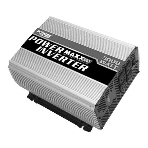
3,000 Watt
Power Inverter
USER'S MANUAL
& WARRANTY INFORMATION
IMPORTANT SAFETY INFORMATION, SAVE THESE INSTRUCTIONS
TO REDUCE THE RISK OF INJURY, USER MUST READ AND UNDERSTAND
THIS INSTRUCTIONAL MANUAL. THIS MANUAL CONTAINS IMPORTANT
INFORMATION REGARDING THE OPERATION AND WARRANTY OF THIS
PRODUCT. PLEASE RETAIN FOR FUTURE REFERENCE.
4140 S.W. 30th Ave., Ft. Lauderdale, FL 33312
Toll Free: (866) 584-5504
www.vectormfg.com
VEC551POB
Advertisement
Table of Contents
Troubleshooting

Summary of Contents for POWER ON BOARD MAXX SST
-
Page 1: Warranty Information
VEC551POB_Manual_080305.QXD 8/4/05 11:09 AM Page 8 Fault Protection Code and Troubleshooting Guide VEC551POB INVERTER POWER SWITCH TURNED ON Trouble/Indication Possible Cause Suggested Remedy No AC output DC input is below Recharge the battery. 10 volts DC input fuse(s) Investigate for short circuit. Replace blown with same type fuse. -
Page 2: Important Safety Instructions
“hot” receptacle terminals. The “neutral” terminals remain This Power On Board product is warranted, to the original purchaser only, to be free of defects in materials powered with respect to the “ground” terminals. -
Page 3: Table Of Contents
Specifications ..........INTRODUCTION Your new Power On Board ®... -
Page 4: Controls, Indicators And Connectors
VEC551POB_Manual_080305.QXD 8/4/05 11:09 AM Page 2 CONTROLS, INDICATORS AND CONNECTORS 12VDC to 145VDC to 145VDC 120VAC Figure 1 shows the front panel of the inverter. The Power Bar Graph Display gives a CONVERSION CONVERSION visual approximation of the output power of the unit. IT IS NOT A VOLTMETER. AC Power is supplied through four 120 Volt AC standard North American household outlets that can accommodate either two- or three-pin AC plugs. -
Page 5: Installation And Operation
VEC551POB_Manual_080305.QXD 8/4/05 11:09 AM Page 4 If the low voltage alarm sounds when the battery is fully charged, follow the steps 2. Connect the RED cable to the RED post marked (+) on the back of the inverter. outlined in the “Troubleshooting” section of this User’s Manual. The alarm will sound Connect the ring terminal to the POSITIVE terminal of the battery. -
Page 6: Care And Maintenance
VEC551POB_Manual_080305.QXD 8/4/05 11:09 AM Page 6 CARE AND MAINTENANCE WARNING Do not connect to AC distribution wiring! Storage CAUTION – Rechargeable Devices 1. Ideal storage temperature range is 32-104°F (0-40°C). Certain rechargeable devices do not operate well from a modified sine 2.


Need help?
Do you have a question about the MAXX SST and is the answer not in the manual?
Questions and answers