Table of Contents
Advertisement
Operating manual
CC
27.09.2011
Also for models with natural refrigerants
Valid for:
K12-cc-NR, K15-cc-NR, K20-cc-NR, K25-cc-NR, K6-cc, K6s-cc-NR
variostat cc
ministat 125-cc, ministat 125w-cc
ministat 230-cc, ministat 230w-cc
ministat 240-cc, ministat 240w-cc
CC-405, CC-405w, CC-410wl, CC-415, CC-415wl
CC-505, CC-505wl, CC508, CC-510, CC-510w, CC-515, CC-515w
CC-520w, CC-525w
CC-805, CC-820, CC-820w, CC902, CC-905, CC-905w, CC-906w
Advertisement
Table of Contents

Related Manuals for Huber K12-cc-NR


Summary of Contents for Huber K12-cc-NR
-
Page 1: Operating Manual
Operating manual 27.09.2011 Also for models with natural refrigerants Valid for: K12-cc-NR, K15-cc-NR, K20-cc-NR, K25-cc-NR, K6-cc, K6s-cc-NR variostat cc ministat 125-cc, ministat 125w-cc ministat 230-cc, ministat 230w-cc ministat 240-cc, ministat 240w-cc CC-405, CC-405w, CC-410wl, CC-415, CC-415wl CC-505, CC-505wl, CC508, CC-510, CC-510w, CC-515, CC-515w... -
Page 2: Table Of Contents
Contents V2.2/09.11 // software V06.10.001 Foreword ......................4 Quick guide for CC-thermostats ................5 Chapter 1: Safety ....................7 Description of Safety and Information symbols ............8 Intended Use and General Safety Instructions............9 Description ....................... 10 Duties of responsible person ................11 Operator requirements ..................11 Machine operator duties .................. - Page 3 Ending CC Temperature control ................67 Filling and air purging an externally closed system ..........68 Draining the machine and an externally closed application........69 Changing thermal fluid / internal cleaning .............. 69 Chapter 4: Interfaces ..................70 Interface modules (RS232/SERIAL, Com.G@te and Web.G@te) and Interface menus . 71 RS232/SERIAL ....................
-
Page 4: Foreword
Foreword Dear Customer, The Huber team would like to thank you for ordering this product. You have made a good choice. We thank you for your trust! Please read and understand the instruction manual thoroughly before operating the unit. All instructions and safety information must be complied with. -
Page 5: Quick Guide For Cc-Thermostats
Quick guide for CC-thermostats Checklist for initial operation: 1. Make sure that the machine is connected correctly and enough thermal fluid is inside. 2. Switch on the unit via the mains switch! 3. Make sure that the over-temperature is set correctly. 4. - Page 6 COM.G@TE allocation and setting (quick guide) POCO (potential free contact) Alarm plug-in connector Signal contact for external monitoring. The connection is designed as a potential free changeover contact. Normally open contact between pin 1 and pin 2. Normally closed contact between pin 2 and pin 3. Contact load: 1A at 24V DC Only use screened lines! AIF Reg-E-Prog Socket Analogue interface, one input channel (programmable) and 3 output channels.
-
Page 7: Chapter 1: Safety
Chapter 1: Safety In this chapter is to be found the following sections: Description of safety and information symbols Intended use and General Safety Information Description Duties of the responsible person Operator requirements Machine operator duties Work area Safety Devices to DIN 12876 (applicable for units with heating) Additional Protection Devices (if provided) Environmental conditions Operating conditions... -
Page 8: Description Of Safety And Information Symbols
Description of Safety and Information symbols Safety information is shown with a pictogram and keyword. The keyword indicates the level of the corresponding danger. Immediate risk to the life and health of Danger! personnel (Serious injury or death). Possible risk to the life and health of Warning! personnel (Serious injury or death). -
Page 9: Intended Use And General Safety Instructions
Intended Use and General Safety Instructions Danger! Non-intended use can result in considerable personal injuries and material damage. No third persons are authorized to make any changes to the machine. The device declaration becomes void, if any modification is carried out without manufacturers consent. -
Page 10: Description
Description These temperature control machines have been designed to be used with either external closed systems (e.g. jacketed reactors) or the internal bath. For temperature control devices with compressor cooling, the low internal volume combined with high performance refrigeration and heating technology, gives a very short cooling and heating time compared with conventional bath technology. -
Page 11: Duties Of Responsible Person
Duties of responsible person The operating instruction is to be kept easily accessible and in immediate vicinity of the unit. Only suitably qualified personnel should operate this unit. Personnel should be properly trained before operating the unit. Make sure that the operators have read and understood the instruction manual. -
Page 12: Safety Devices To Din12876
Safety Devices to DIN12876 Low-liquid level protection Adjustable over-temperature protection Table 2 – Classification of laboratory circulators and laboratory baths Class Heat transfer Technical requirement Marking designation liquid non-flammable overheating protection adjustable overheating protection flammable adjustable over-temperature protection and additional low-liquid level protection Usually water;... - Page 13 To 1. Temperature control machines with classcial float The most common and known type of level monitoring is the mechanical float. The float swims on the surface of the thermal fluid in the bath, and leads to a switching system. Depending on the level of the thermal fluid, the electronics will either signalize an OK state (with sufficient filling of the thermal fluid) or a non OK state (with insufficient filling of the thermal fluid).
-
Page 14: Additional Protection Devices
Additional Protection Devices Auto-Start function Alarm function Warning messages General unit messages Danger! Emergency Procedure: Disconnect Electrical Power! Turn the Mains isolator (36) to “0”! Dangerous liquid / vapours from temperature control unit or connected hoses (very hot, very cold, dangerous chemicals) and / or fire / explosion / implosion: Evacuate the area, following local regulations and procedures to prevent injury or loss of life! Refer to the MSDS Safety information for the thermal fluid concerned! Environmental Conditions... -
Page 15: Operating Conditions
Operating conditions Please make sure that the application and system performance is dependent upon the temperature range, viscosity, and flow rate of the thermal fluid: Please ensure that the power supply connections are correctly dimensioned. The temperature control device should be located so, that sufficient fresh air is available even when working with water cooled units. -
Page 16: Location
Use only recommended materials to maintain the unit warranty. Further information on corrosion, (appearance and avoidance) can be found on our website www.huber-online.com under "Download / Safety data sheets thermal fluids / Characteristics of water". -
Page 17: Thermal Fluids
For chillers we recommend as thermal fluid a mixture of water and glycol (a mixture is recommended that permits a temperature down to -25°C). Information on water quality can be found on our website (www.huber- online.com) under "Download Safety... -
Page 18: Chapter 2: Electronics And Operation
Chapter 2: Electronics and operation The following sections are to be found in this chapter: CC-Pilot Information display Real time clock Operation Operation using the rotary knob Operation using the simulated Number Pad Main menu points Compact menu Comfort menu Com.G@te menu Function numbers and their meaning Configure user menus... -
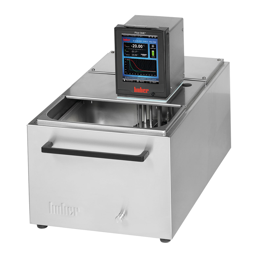
Page 19: Cc-Pilot
CC-Pilot Locking 60) Touch screen and graphic display 61) Key and rotary knob 62) ESC key 63) Key 1 (Soft-key 1) 64) Key 2 (Soft-key 2) 65) Key 3 (Soft-key 3) 66) LED temperature display 68) LED status display... -
Page 20: Information Displays Cc
Information Displays CC The following information displays are available: 1. Graphical display (60) The most important display, giving details of standard parameters (set-point, current temperature, set-point limits), as well as menu options and error messages. 2. LED temperature display (66) The green LED display shows the current temperature. - Page 21 Description of individual Fields Field 1: Display Current value This field shows the current internal temperature of the unit and, if an external sensor is connected, the current process temperature. Field 2: Display set-point This field displays the current set-point. Field 3: Display Graphic temperature This field shows the internal and process temperatures in graphical format.
- Page 22 Field 10: Display delta T This field displays the delta T value (max. admissible difference between process and internal temperature). This value may be set within a range of 0…100K under the main menu point limits / delta T limits. This field is active only with a connected process sensor and when the temperature control mode process temperature is activated.
-
Page 23: Real-Time Clock
Real-time clock Rechargeable Battery The Unistat Pilot as well as CC-Pilot (for temperature control devices with CC-Pilot) are equipped with an internal, battery-powered clock that runs even when the unit is turned off. When the unit is powered up, the actual date and time are uploaded to the unit. The capacity of the battery means allows the clock to continue to run for a number of months. -
Page 24: Operation Cc
Operation CC Please note, there are multiple possibilities to operate the machine. 1. Operation via function keys T1 to T3 (63, 64, 65), together with information given in the lowest line of the graphic display (60). 2. Operation via the rotary knob / key (61) By pressing the key / rotary selector (61) one can choose the individual fields. -
Page 25: Cc Operation Using The Rotary Knob
Depending on the E-Grade level, an upgrade can be made at any time with lower and middle levels, and the appropriate menu points will be displayed in the Graphic display (60). Please contact us at +49(0)781-9603100 or per e-mail under info@huber-online.com concerning information regarding upgrades. -
Page 26: Cc Operation Using The Simulated Number Pad
CC Operation using the simulated Number Pad Function number menu Keyboard Function number Set-point New value F 0 Set-point Maximum value 50.00 Minimum value -20.00 <- Function number menu: Pressing the Funct.No. area at the bottom of the graphic display (60) will bring up the Number pad display. -
Page 27: Main Menu
Main menu The following functions are available: Compact menu Comfort menu Control parameters Acoustic alarm Comfort menu Auto-Start Display modes Clock Enter program Com.G@te (with connected Com.G@te only) Overtemperature protection Compact menu Pump settings Compressor automatic (not valid for all units) Set-point Control parameters Set-point limits... -
Page 28: Compact Menu
Compact menu Control parameters: The default setting is Automatic control parameter. CONTROL PARAMETERS: CONFIGURATION MANUAL AUTOMATIC / MANUAL Select auto./ manual CONTROL PARAMETERS: SELECTION: Config. automatic Config. manual param. Change control parameters Manual control parameters Reset control parameters Display control parameters Automatic control parameters Go back Display Parameter... - Page 29 After selecting the main menu point Control parameters, the following functions are available: Select autom./manual Config. automatic Config. manual parameters Reset control parameters Display parameters Go back Select Autom. / Manual (Select Automatic / Manual) Application of the automatically detected or manually entered parameters, in order to regulate the temperature.
- Page 30 2. With preliminary Test: To achieve the best control results, select With preliminary Test in the controller settings. The control parameters will be identified within the limits of the min. and max. set-points. Temperature control will also take place at the set-point limits. Please be sure to have set these correctly.
- Page 31 Comfort menu Here one can switch to the whole range of functions. Please also note the chapter on Comfort menu, where further functions of the comfort menu are described. Display modes Following functions are available: 1. Standard: Values are displayed numerically (valid for all temperature control devices with Unistat Pilot and CC-Pilot).
- Page 32 Example: Indication when choosing Large display TInternal °C -20.5 TProcess °C -20.1 Tset-point °C -20.0 35 °C Temperature control is active Enter program This corresponds to Function F20 in the Funct.-no. menu. Here it is possible to write new programs, or programs already written can be edited and changed or erased.
- Page 33 COMPACT MENU: Enter program Segment 1 Select Program: Seg.: 1 Program 1 SP: 20,00°C Time/min: 1 Mode: internal Stability: Temp Program 10 AIF OUT: off AIF%:0 Return to main menu Funct.: linear Tconst./ min 0 POCO: off Program 01 contains 00 segments BACK Segment 1...
- Page 34 To create a new program, continue as follows: 1. Select the menu point Enter program from the Compact / Comfort menu. 2. Select the program number to be used. Information on the number of segments from the program currently used etc is shown in the lower part of the graphic display screen (60).
- Page 35 Over-temperature protection Cut-off limits can be set in the heating chamber / heating. Please note chapter on setting the Overtemperature protection (OT). Program Start & stop Corresponds to function F23 in the Funct. No. menu. Here you can start, interrupt or end a program.
-
Page 36: Comfort Menu
Comfort menu Acoustic alarm Here you have the option to activate / deactivate the acoustic signal output. Auto-Start (after power on) This corresponds to Function F5 in the Funct.-no. menu. This allows the start-up condition, after mains failure to be defined. The following is true: OFF / Standby After power loss ... - Page 37 Compact menu Here one can switch to the limited possibilities of the compact menu. Compressor Automatic Corresponds to Function F35 in the Funct.-no. menu. This is used to select the operating mode of the compressor. The default setting is always on. Automatic: The compressor control is set to switch on and off as required by the unit.
- Page 38 Enter program A description on this menu point can be found in chapter Compact menu. Factory default This section allows the different areas of the temperature control unit to be reset to the factory default. This can be a relatively quick way of changing the unit settings. Unit control data: Resets the set-points, set-point limits, temperature control mode, to the factory-set default values.
- Page 39 Protection functions Following functions are available: 1. Internal sensor high limit alarm 2. Internal sensor low limit alarm 3. Process sensor high limit alarm 4. Process sensor low limit alarm 5. Warning time level (only valid for immersion thermostat CC-E and combinations using the immersion thermostat CC-E) 6.
- Page 40 Other temperature: Input of a previously measured temperature pair. Service This menu is only available in service mode, and may only be accessed after contacting Huber. It allows the unit’s internal sensors and other data to be directly read, for service purposes.
- Page 41 Set-point A description on this menu point can be found in the chapter on the Compact menu. Set-point limits A description on this menu point can be found in the chapter on Compact menu. Settings (others) Here, information concerning your application may be entered or read out. The values input here will be considered when controller parameterisation is taking place (please see chapter on Control parameters) The following functions are available under the menu point Change thermal fluid:...
- Page 42 Time scale The time display can be displayed in various formats (hh, min, sec). set-point Corresponds to the Function F4 in the Function-no. menu. The input of a 2 or alternative set-point is done in the same way as the normal set-point under the menu point set-point.
-
Page 43: Com.g@Te Menu
Com.G@te menu Here, the functions (analogue interface, RS232/RS485, ECS-Standby, POCO Alarm) used in connection with an external control (e.g process control system “PCS”) are listed. COM.G@TE: Analogue interface RS232/RS485 ECS Standby POCO Alarm Return to main menu DIGITAL INTERFACE: ANALOGUE-INTERFACE: Select RS232/485 Config. - Page 44 Analogue Interface ANALOGUE-INTERFACE: Config. input Config. output Go back AIF INPUT FUNCTION: ON CABLE BREAK: ANALOGUE INPUT AIF ->Input off Trigger an alarm AIF–Input - Function AIF ->Internal temp. No alarm, normal operation On cable break AIF ->Process Temp. Go back Cfg.
- Page 45 ANALOGUE-INTERFACE: Config. input Config. output Go back SOURCE ANALOGUE OUT: ANALOGUE OUTPUT: No output AIF-Output - range Set-point Cfg. input range Internal temp. Adjustment Process temp. Reset AIF output Manual preset Show table values Programmer Go back RS232 / 485 Pump Press.
- Page 46 Settings: 1. Settings on temperature / current range Select analogue interface / config. input / adjust measurement range Enter the temperature range to correspond to 0/4-20mA (T1=0 °C, T2=100 °C). 2. Select input signal Select the input signal (AIF-> set-point) via analogue interface / config. input / AIF-Input - Function 3.
- Page 47 RS232/RS485 (Digital Interface) Following functions are available: 1. Select RS232/485 (option between RS232 and RS485) 2. Baudrate (selection of transmission speed) 3. Slave address (Selecting a bus address, only when using RS485) 4. Test dig. Interface (command TI is send via RS232) 5.
- Page 48 Condition POCO ON means temperature control is activated. Condition POCO OFF means temperature control is not activated. Control by RS232: The relay is controlled via an RS232 command. Therefore please note our Huber- Software. Check process temperature.: A measured temperature check for the PROCESS SENSOR providing it is not the control sensor.
- Page 49 Unipump with echo: This function is used to monitor if the Unipump being controlled by the POCO is operating in synchronisation with the Unistat’s own pump. The operating status of the Unipump can be signalled via a normally open contact by connecting to a “level” connector.
-
Page 50: Function Numbers And Their Meaning
Function Numbers and their meaning A detailed description of the functions, as well as an alternate operation for the menu guide can be found in the chapter Compact-/ Comfort-/ Com.G@te menu F0 Set-point minimum set-point <= set-point <= maximum set-point If an attempt is made to enter a set-point outside these limits, then a warning message will be shown on the display (60) and the set-point will not be accepted. - Page 51 F8 POCO - programming The options for the potential free contact are given and described in the earlier Potential free Contact section the Com.G@te menu of this manual (Pot. free Contact). F9 Control parameters Please see chapter Control parameters in the Compact menu for detailed description. F10 Machine messages Information on the machine about condition (status, warnings and faults).
- Page 52 F30 Set date Setting the date. F31 Set time Setting the time. F33 Set over-temperature protection Setting the over-temperature protection. Please note chapter on setting the over- temperature switch. F34 Air purge Start / Stop air purge F35 Compressor automatic This is used to select the operation of the compressor: Default setting is always ON Automatic: The compressor automatic is set to switch on and off as required by the unit.
- Page 53 F49 Unit name This function displays the unit model number. F50 Input password Used only for Service. Contact Huber for further information. F52 Factory default This functions allows to reset the unit to the factory default. F55 Degassing mode Activating the degassing mode.
- Page 54 F90 Language / Sprache Selecting the language. F98 Software version Display of software versions. F103 Set-points refrig. (Set-points refrigerating machine) Used only for Service. F106 Proc. high limit alarm (Upper alarm limit process temperature) A description of this function is given in the Safety Functions section of the Comfort menu.
- Page 55 F131 Display mode normal Choosing standard display mode. F135 Adj. analogue input (analogue interface input current adjustment) Fine adjustment of the 0/4-20mA or 0-10V input current range. Using this function the current limits of the 0/4-20mA or 0-10V analogue input signal can be calibrated. See also chapter on the Com.G@te.
-
Page 56: User Menu - Config
User menu – config. Using this main menu point up to seven different operational modes (user modes) can be set up. This is comparable to the main menu point Compact menu. However here the user menu can be stopped and edited at any time. There is also the ability for an administrator to create and save menu lists for individual users. -
Page 57: User Menu - Select
User menu - select This option can be used to configure a user menu to be operated like a new main menu. In this case only the main menu points are accessible that have been previously activated through the main menu point “User menu – config.”. A user menu can only be selected if the administrator has entered the correct password (figure between 0 an 65535). -
Page 58: Chapter 3: Connect The Machine, Fill And Prepare For The Required Application
Chapter 3: Connect the machine, fill and prepare for the required application Power connection Start up Connecting an externally closed application (reactor) Switching on the temperature control unit Setting the over-temperature (OT) switch Setting the level indicator with capacitive level identification (for chillers only) Setting set-point limits Entering a set-point Starting temperature control... -
Page 59: Power Connection
Power connection . Danger! Check to make sure that the line voltage matches the supply voltage specified on the identification plate or data sheet. We disclaim all liability for damage caused by incorrect line voltages! Safety instructions Only connect the unit to a power socket Danger! with earthing contact (PE –... -
Page 60: Water-Cooling (Valid For Units With Water Cooling)
Water-cooling (valid for units with water cooling) A cooling water controller is used in Huber tempering devices with water cooling, in order to reduce the cooling water consumption. This only allows as much cooling water to flow as is required by the current load situation of the tempering device. Only little cooling water is consumed, if the required refrigerating capacity is low. -
Page 61: Operation As Bath Thermostat (Valid For Temperature Control Units With Baths)
This may lead to a later safety switch off (low level protection) during temperature control. Always switch off temperature control before taking the sample out of the bath. e.g. K12-cc-NR Variostat with Variostat bath Please note, that combinations using the Variostat with Variostat baths do not have the whole space (and volume) of the Variostat bath available (see picture above). -
Page 62: Connecting An Externally Closed Application (Reactor)
Connecting an externally closed application (reactor) Remove the thread covers from the unit´s circulation flow (1) and circulation return (2). Make sure that the hose material is compatible with the thermal fluid and temperature range being used. The appropriate size spanners can be taken from the table below. In order that the application can be driven correctly, and that no air bubbles remain in the system, ensure that the unit´s circulation flow (1) is attached to the lowest connection on the application, and the unit´s circulation return (2) is attached to the highest... -
Page 63: Switching On The Temperature Control Unit
A shutdown of the unit in this situation would be fatal. The Peter Huber Kältemaschinenbau GmbH offers the possibility to use the cut-off mode Process Safety. Temperature control (cooling) and circulation remain on. - Page 64 Over-temperature protection CHARACTERISTICS: OT limit: heating OT Mode Display all OT values Return to main menu Protection overtemperature CHARACTERISTICS: OT limit: heating Actual OT values OT Mode Sensor heater 1 19.0°C Display all OT values Return to main menu Tripping points Setting OT ht.1 35.0°C Code for OT input OT Mode...
- Page 65 Setting the safety value: Select the Over-temperature protection from the main menu. Choose the menu point OT limits: heating. A code generator (random generator) will give out a code via the graphics display. This code has to be entered when requested (a deliberate and knowing action).
-
Page 66: Setting The Set-Point Limits
Setting the set-point limits The minimum and maximum set-point limits provide safety for the equipment. These limits should be set before starting temperature control and when changing the thermal fluid in relation to the temperature range of the thermal fluid. The maximum set-point limits the set-point input of the outlet temperature. -
Page 67: Ending Cc Temperature Control
Ending CC Temperature control The temperature control can be ended at any time by pressing the function key T3 (65). The temperature control and circulation is immediately stopped. Alternatively, to set the unit to standby mode and use the main menu point Start & Stop - menu point Stop temperature control. -
Page 68: Filling And Air Purging An Externally Closed System
MSDS information. If thermal fluid is spilled over the unit, the unit should be immediately turned off, and Huber-trained personnel consulted. Failure to observe the above precautions may mean that the unit will not comply with all of the requirements of DIN EN 61010-2-010. -
Page 69: Draining The Machine And An Externally Closed Application
Draining the machine and an externally closed application General Before draining the unit, the thermal fluid should be at ambient temperature (approx. 20 °C). If not, let the machine run with a set-point of approx. 20 °C for a few minutes until the thermal fluid is at a safe temperature. Connect one end of a suitable drain hose to the drain of the unit (8), and place the other end into a suitable container (make sure the hose and container materials are compatible with the thermal fluid being used. -
Page 70: Chapter 4: Interfaces
Chapter 4: Interfaces The following sections can be found in this chapter: Interface modules RS232/Serial Mutual functions Com.G@te/Web.G@te Specific functions Com.G@te Specific functions Web.G@te... -
Page 71: Interface Modules (Rs232/Serial, Com.g@Te And Web.g@Te) And Interface Menus
Web.G@te) and Interface menus General information: Peter Huber Kältemaschinenbau GmbH offers several possibilities of external analogue and digital control. The interactive and modular Plug&Play interface technology makes it possible to retrofit interfaces (see possibilities below) even for the smallest CC temperature control units. - Page 72 LAI Command Set The master queries whether the slave 01 is connected to the bus. Master query: [M01V07C6\r Command structure: Start signal (5Bh) 1 Byte transmitter identification M (4Dh) for master or S (53h) for slave 1 Byte Slave address 01…99 2 Byte Identifier data group 1 Byte...
-
Page 73: Rs232/Serial
The following interfaces are available: 1. RS232/SERIAL (Standard Interface! Included in all CC units with CC-Pilot) 2. Com.G@te internal or external version depending on the unit (Extension of an analogue interface or a further digital interface) 3. Web.G@te internal or external version depending on the unit (Control possible via Intranet, Internet, USB…) Caution! With plug-in connections subject to a higher voltage than 60 V (AC) and 40 V (DC) -
Page 74: Mutual Functions Com.g@Te/Web.g@Te
Mutual functions Com.G@te/Web.G@te PoKo (potential free contact) Alarm plug connector Signal contact for external monitoring Observe the functional options, which the PoKo provides in the main menu. The potential free contact (PoKo) signals the condition of the temperature control device by means of the contact position. A closed operating contact means ready status (must be set via the menu). - Page 75 RS232 / RS485 Serial Socket A PC, PLC or a process control system (PCS) can be connected to this socket, in order to remotely control the controller. Alternatively, connecting to a RS485 bus is also possible (not valid for the Web.G@te). Before connecting the line, check and if necessary adjust the settings in the menu Digit.
-
Page 76: Specific Functions Com.g@Te
Specific functions Com.G@te (internal version) (external version) The signal connectors have been designed according to the NAMUR standard AIF Reg-E-Prog Socket The analogue interface, one input channel (programmable, option current or voltage signal possible) and 3 output channels (1 programmable). The analogue interface of the Com.G@te is programmed in the Main menu. -
Page 77: Specific Functions Web.g@Te
Designation Level Test (Bridge to terminal 2 „Present“) Level – (GND) Level + (Normally open contact) Specific functions Web.G@te (internal version) (external version) This device is designated for the operation behind a firewall, provided that the local subnetwork is connected to the internet or with another highly random field network. To provide safety for the LAN the standard rules of the IT apply. - Page 78 This interface enables communication via the TCP/IP protocol to communicate with the thermostat via the above mentioned protocols (PP, LAI, Namur). Temperature profiles can be recorded by using the Huber Spysoftware. The port for this communication is 8101. Access can be granted to the internal webserver.
- Page 79 USB Device The operating mode of the USB device is basically the same as for the Ethernet (see description on Ethernet interface). Only the URL/IP address differs from the one used for Ethernet. To connect several Web.G@tes onto one PC it is necessary to be able to allocate multiple ports to those different Web.G@tes.
- Page 80 Afterwards the subnet mask has to be entered. Please contact your administrator. SpyWeb: SpyWeb is a rudimentary Spy surface (data recording software for Huber). TI/TE/SP can be visualized on the right as well as on the left Y axes. The first 5/30 min or 24 hours are visible.
- Page 81 Customer Support. Connection to a VPN server (VPN Settings) There exists the possibility to connect to e.g the Huber Service Center via a VPN connection (highly coded connection via the internet). This connection can only be carried out via the Web.G@te!
-
Page 82: Chapter 5: First Aid For A Fault Condition
Chapter 5: First aid for a fault condition The following sections can be found in this chapter: Messages Display Error Messages Alarm and Warning codes Exchange of the electronics / Remote Control Maintenance Decontamination / Repair Cleaning the surfaces Plug contacts... -
Page 83: Messages
Messages Messages which occur can be split into Warnings and Alarm messages. Please note that alarms generally cause the machine to stop temperature control. An alarm message is immediately displayed as text on the graphic display (60). After the reason for the alarm has been repaired, the machine must be switched off using the main switch (36), and then switched on again in order to reset the alarm. -
Page 84: Display Error Messages
(36) and the error condition corrected. The unit can then be turned on again. If an alarm occurs during the unit start up and self-test, please contact Huber for advice. Soft alarms (error codes -1024 to -2047) These alarms also cause the temperature control to be immediately stopped. -
Page 85: Alarm And Warning Codes
Alarm and Warning codes Hard Alarms (not resettable) Code Message Action Over-temperature reached Please see chapter on setting the over-temperature Low-level alarm release Fill with sufficient thermal fluid actual value internal Check alarm limits exceeded the alarm temperature actual value-internal Check alarm limits exceeded the alarm temperature actual... - Page 86 Pump pressure has dropped Activate air purging, degassing program. Please see corresponding chapters in the instruction manual. No pump pressure seen over a Activate air purging, degassing program. Please see longer time period corresponding chapters in the instruction manual. No valid measured values of the Please contact us or our service partners internal sensor No valid measured values of the...
- Page 87 -143 The LT Pressostat has operated Please contact us or our service partners -144 The MT Pressostat has operated Please contact us or our service partners -148 Reporting contact of the pump Please contact us or our service partners has triggered -149 Phase Relay for the pump motor Right-hand (3 phase, 400V) rotation of the power supply...
-
Page 88: Exchange Of The Cc Electronics / Remote Control
-2048 Internal actual value Check alarm limits exceeded alarm temperature -2049 Internal actual value has fallen Check alarm limits below alarm temperature -2050 Check alarm limits Process actual value exceeded alarm temperature -2051 Process actual value has fallen Check alarm limits below alarm temperature -2052 Analogue... -
Page 89: Maintenance
(36) and disconnect it from the mains. There are few user-serviceable parts inside the unit. Other than the items listed below, maintenance should be carried out by Huber-trained and authorised personnel. Cleaning cooling fins (for air cooled machines with compressors only) To ensure that the temperature control unit will give the maximum cooling power the unit has to be freed from dirt (dust) from time to time. -
Page 90: Decontamination / Repair
We have prepared a document to simplify this process. This is available in the appendix, and at our website www.huber-online.com. Cleaning the surfaces A normal steel cleaning spray is suitable for cleaning the stainless steel surfaces. -
Page 91: Chapter 6: Taking The Machine Out Of Service
Chapter 6: Taking the machine out of service The following sections can be found in this chapter: Decommissioning Transport Disposal... -
Page 92: Decommissioning
Decommissioning Safety notice and policy Caution! Injury to persons or property possible: Danger of slippage due to contaminated floor and working area. Danger of tipping due to insufficient stability. Danger of electric shock due to faulty power connection. Danger of burns at extreme temperatures if touched. Danger of chemical burns of the eyes, skin or airway due to emission of dangerous vapours (with the appropriate thermal fluid). -
Page 93: Transport
Transport The unit is now decommissioned and ready for transportation. The original packing material should be used as far as possible, and the unit must always be transported in the upright position. Items such as the controller and sight glass should be protected from transport damage. The unit should not be transported on its rollers, or mounting feet. - Page 94 Ethanol spülen. Vielen Dank! Please note that if you’re using none Huber heat transfer fluids we have to flush the system before we start with your repair. The resulting costs have to be added onto your bill. You can reduce your repair costs by flushing your system with ethanol before return.
Need help?
Do you have a question about the K12-cc-NR and is the answer not in the manual?
Questions and answers