Table of Contents
Advertisement
Advertisement
Table of Contents

Subscribe to Our Youtube Channel
Related Manuals for AVERATEC All-In-One PC

Summary of Contents for AVERATEC All-In-One PC
- Page 2 Regulations Information This equipment has been tested and found to comply with the limits for a Class B digital device, pursuant to part 15 of the FCC rules. These limits are designed to provide reasonable protection against harmful interference in a residential installation.
- Page 3 This device complies with part 15 of the FCC Rules. Operation is subject to the following two conditions : 1. This device may not cause harmful interference. 2. This device must accept any interference received, including interference that may cause undesired operation. Before You Start...
-
Page 4: Optical Device Drive Notice
Optical Device Drive Notice CAUTION This appliance contains a laser system and is classified as a “CLASS 1 LASER PRODUCT.” To use this model properly, read the instruction manual carefully and keep this manual for your future reference. In case of any trouble with this model, please contact your nearest “AUTHORIZED service station.”... -
Page 5: Macrovision Notice
Macrovision Notice This product incorporates copyright protection technology that is protected by U.S. patents and other intellectual property rights. Use of this copyright protection technology must be authorized by Macrovision, and is intended for home and other limited viewing uses only unless otherwise authorized by Macrovision. Reverse engineering or disassembly is prohibited. Safety Instructions 1. - Page 6 10. If any of the following situations arises, get the equipment checked by a service personnel: • The power cord or plug is damaged. • Liquid has penetrated into the equipment. • The equipment has been exposed to moisture. • The equipment has not worked well or you can not get it work according to Users Manual. •...
-
Page 7: Weee Statement
WEEE Statement Before You Start... -
Page 8: Before You Read
AVERATEC is a trademark or registered trademark of TriGem Computer, Inc. in the United States and/or other countries. All other product and brand names are trademarks of their respective owners. -
Page 9: Table Of Contents
Using the Wireless LAN Table of Content viii Using the Multi-Card Reader Using the Internal Microphone What is the Averatec All-In-One PC? Entering into the System BIOS Setup BIOS Setup Menu Replacing the Main Memory Using the Optional VESA Mount Kit... - Page 10 Chapter Introduction Chapter 1 Introduction...
-
Page 11: What Is The Averatec All-In-One Pc
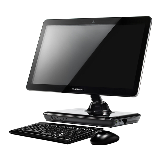
What is the Averatec All-In-One PC? The Averatec All-In-One PC is an all inclusive desktop PC that is designed for quick installation and easy use without taking up much desk space. Integrated PC and LCD monitor The Averatec All-In-One PC is equipped with a 18.4" wide LCD monitor and fully functional PC. Nothing else is needed. The All-In-One PC is designed to be a complete plug-and-play system. - Page 12 Designed for the Internet The Averatec All-In-One PC is designed for the Internet, so you can send emails or instant messages, talk to friends over VoIP or just surf the web with ease. Efficient computing The Averatec All-In-One PC is designed to support all your basic computing needs and then some. With this PC, you can enjoy the most popular tasks such as word processing, internet browsing and basic gaming.
- Page 13 Chapter Getting Started Chapter 2 Getting Started...
-
Page 14: Turning On And Off
Turning On and Off Press the power button on the front side of the PC. Case 1 Click Start to turn off computer. 1. Click Start and select Turn off computer. Turn off computer screen displays. 2. Click Turn Off. Chapter 2 Chapter 2 Getting Started... - Page 15 Press the power button on the front side of the PC. Case 2 After closing all programs,the PC will be turned off. If the system is operating abnormally, you can reboot the PC by holding down the power button until the PC turns off. Then press the power button again to boot back up. Case 3 Power saving mode.
-
Page 16: Adjusting The Brightness Of The Monitor
Adjusting the Brightness of the Monitor You can adjust the brightness by clicking the brightness control button on the front side of the PC. There are 5 levels of LCD brightness adjustment available. Each press of the brightness control button will cycle through each level. -
Page 17: Adjusting The Speaker Volume
Adjusting the Speaker Volume The Speaker volume level can be adjusted easily with the button located on the Front side of the PC. Speaker Speaker Volume button (Up/Down) To adjust the volume level, press the left volume button to increase the volume level and the Right volume button to decrease the volume level. -
Page 18: Connecting External Speakers
Connecting External Speakers Connect the speakers to headphone jacks Speakers (optional) To set the audio configurations, refer to the follow steps: 1. Double click the Controls IDT Audio Setting icon. Chapter 2 Getting Started... - Page 19 When you finish the setting, click The Averatec All-In-One PC has built-in speakers on the base of the system.You can adjust the volume by clicking the volume adjustment buttons located on the front side of the PC and / or by using the volume control feature in Windows XP.
-
Page 20: Using The Optical Drive
Insert CD/DVD in the CD/DVD drive and place CD/DVD label upside front. Press the CD/DVD Drive. 3. Eject CD/DVD Press the Eject button of the CD/DVD drive on the left side of the Averatec A1 PC. You can then remove the CD/DVD. Chapter 2 Getting Started... - Page 21 Note If you can not eject a CD/DVD from the drive, click Start, choose Computer, right-click on the CD/DVD drive that the CD/DVD is in and choose Eject in the popup menu. If you can not eject a CD/DVD from the drive by pressing the eject button and choosing the Eject menu, insert the paper clip into the emergency eject hole as far as it will go then the tray will be slightly open.
-
Page 22: Connecting To The Internet
Connecting to the Internet 1. Press the power button and the Windows XP start screen will appear. Connect a LAN cable to the LAN connector as shown in the figure below. 2. Configure the communication settings for the system based on your communication environment. -
Page 23: Using Your Webcam
Using Your Webcam You can take photos and chat with your friends. Take photos To take photos, follow the next steps : 1. Double click the CyberLink YouCam icon( ) on the desktop. 2. The CyberLink YouCam will be run and a green light on the webcam LED indicates your PC is ready to take photos. 3. - Page 24 To chat with video, both your system and the system of the person you want to chat with must have a web camera or a CCD camera installed. You also need to download and install a messenger program. The screen that you will see varies depending on the type of the messenger program you’re using.
- Page 25 2. Right-click on your chat partner and then select Start a Video Conversation, as illustrated below. Note If the web-camera setting is not configured, you will see the below screen. Run the wizard for setting the web-camera by following the message on the screen.
-
Page 26: Using The Wireless Lan
Using the Wireless LAN To use a wireless network in an office environment where APs (Access Points) are installed, see the following instructions. (The example used here explains how to use the basic Windows configuration features to configure the system. You can also use the program that comes with the wireless LAN card to configure the network.) 1. - Page 27 3. When the connected window appears, confirm the settings and then click Close. 4. Once connection is successfully established, the network icon on the status bar will indicate the status change. Chapter 2 Getting Started...
-
Page 28: Using The Multi-Card Reader
Using the Multi-Card Reader Averatec's A1 PC accepts 4 types of multi-media cards into the multi-card reader slot on the right side of the PC. SD (Secure Digital™), MS-PRO™, MS-PRO™ Duo, MS(Memory Stick™), MMC(MultiMediaCard™), RS-MMC To insert correctly, refer to the pictures. The cards are not inserted completely, the tip of the cards will remain out of the slot. -
Page 29: Using The Internal Microphone
Using the Internal Microphone Your PC comes with a built-in internal microphone near the power button on the left of the computer. Use the built-in internal microphone to record sound for your webcam videos, and to use instant messenger or chat software to have video chats online. - Page 30 Chapter System BIOS SETUP Chapter 3 System BIOS SETUP...
-
Page 31: Entering Into The System Bios Setup
For System BIOS Setup, only change the items that you need. Note that incorrect settings of the BIOS Setup could result in a system malfunction. Entering into the System BIOS Setup After powering on the system, press <Del> to enter the System Setup screen. Function Key Command Description... -
Page 32: Bios Setup Menu
BIOS Setup Menu Sets most standard specifications for the system, such as the time, date. Sets up key items related to the system’s performance. Chapter 3 System BIOS SETUP... - Page 33 You can set the boot sequemce. Sets up a password to prevent any unauthorized user from accessing the system. Chapter 3 System BIOS SETUP...
- Page 34 Set up Password 1. On the initial System Setup screen, Go to Change Supervisor Password, and then press <Enter>. 2. On the following screen, enter the password and then press <Enter>. Enter New Password Confirm New Password Then enter the same password again and press <Enter>. 3.
- Page 35 Save Changes and Exit Save the changes you have made and exit the utility. Discard Changes Exit the utility without saving the changes you have made. Discard Changes Aban your changes and reload the previous configuration before running the utilityt. Load Optima Defaults Select this item to load the default settings for optimal system performance.
- Page 36 Chapter Expansion of the system Chapter 4 Expansion of the system...
-
Page 37: Replacing The Main Memory
Replacing the Main Memory There may come a time when you want to expand the main memory capacity. When expanding the main memory, make sure that the specifications of any newly replaced memory currently installed memory are the same. The following instructions are provided to those who are familiar with system assembly/disassembly in order to help them to find the memory specification. - Page 38 To fix the LCD panel, fold it until the latch snap into place as shown in the figure. Spread the soft thing such as cloth over the flat surface and face down the LCD panel. (Be careful not to damage the LCD panel.) To firm the system module, insert the flat things (such as the books) between the LCD and system module.
- Page 39 Remove the screws and system cover as shown in the figure. 3. Remove the screws and metal cover. Chapter 4 Expansion of the system...
- Page 40 4. Replacing the main memory To replace the memory on the socket, pull the latches on both edges of the socket away at the same time. The memory wiill pop up about 30 degrees. Remove it from the socket. Align the notches of the SO-DIMM memory with the slot keys of the socket, this allows the memory to be inserted. Insert the memory into the socket at a slight angel (about 30 degrees) firmly, and gently press down the memory until both latches snap into place.
- Page 41 5. Replace the metal cover and fix with the screws. Chapter 4 Expansion of the system...
- Page 42 6. Replacing the system cover and the CD drive Replace the system cover and fix with the screws. Replace the CD drive and fix with the screws. Chapter 4 Expansion of the system...
- Page 43 7. Adjust the LCD panel for convenient using. 8. Checking memory capacity Once memory installation is complete, restart the system. If an error message related to the memory capacity appears upon booting, press the Del key to enter the system setup screen. Save the setting and exit. Chapter 4 Expansion of the system...
-
Page 44: Using The Optional Vesa Mount Kit
Using the Optional VESA Mount Kit Your system has four VESA Mount holes on the bottom surface for using the optional VESA Mount kit. To use it, follow the next steps: 1. Turn off your system and remove all cables. 2. - Page 45 3. Fold the LCD panel. 4. Face down the LCD panel on a soft and flat surface to locate the mounting holes on the bottom of your system. (Be careful not to damage the LCD panel.) 5. To firm the system module, insert the flat things (such as the books) between the LCD and system module. 6.
- Page 46 Note The mounting hole pattern of your system is 100 mm x 100 mm. To purchase the optional VESA Mount kit, please refer to this size. Hole Removing the hinge lock clip To remove the hinge lock clip, follow the next steps: Unfold the LCD panel.
- Page 47 Chapter 4 Expansion of the system...
Need help?
Do you have a question about the All-In-One PC and is the answer not in the manual?
Questions and answers