
Subscribe to Our Youtube Channel
Related Manuals for Radio Engineering Industries BUS-WATCH


Summary of Contents for Radio Engineering Industries BUS-WATCH
- Page 1 Digital BUS-WATCH® User Manual Installation Manual Radio Engineering Industries, Inc. 6534 L Street Omaha, Nebraska 68117 402-339-2200...
-
Page 2: Table Of Contents
Digital BUS-WATCH® IV Security Cabinet Mounting Long Term Storage SYSTEM INSTALLATION System Wiring Digital BUS-WATCH® IV External Record Indicator / Event Mark Button Harness Digital BUS-WATCH® IV GPS Antenna Module Harness Digital BUS-WATCH® IV Vehicle Sensor Options Harness DVR Connection Instructions Speedometer Harness Wiring Instructions Digital BUS-WATCH®... - Page 3 Alarm Record Menu Alarm Trigger Options Alarm Record Options Audible Alarm Options Set Record Timers Screen DIGITAL BUS-WATCH® IV CD-ROM DIGITAL BUS-WATCH® IV SYSTEMS RELATED PART NUMBERS TYPICAL CAMERA LENS VIEWING ANGLES SPECIFICATIONS Radio Engineering Industries, Inc. 640333 Rev 0 -- 1/1/2006...
-
Page 4: List Of Figures
Digital BUS-WATCH ® LIST OF FIGURES Figure 1 ……...………. BUS-WATCH® Components……...……...……...……...……...……...……..…. 5 Figure 2 ……...………. System Drawing ………………….……...……...……...……...……..…...……...… 6 Figure 3 ……...………. Camera System Options ...………….……...……...……...……...……...……...……. 7 Figure 4 ……...………. Initial Drive Warming Screen Shot …...……….……...……...……...…..……..10 Figure 5 ……...………. System Wiring ………………………...……...……...……...……...……..…...….. 12 Figure 6 ……...………. -
Page 5: Introduction
Digital Video Recording system encased in a tamperproof, lockable steel security cabinet and surveillance cameras of sturdy steel housings. As an option, the Digital BUS-WATCH® IV can monitor and record vehicle functions such as warning lamp operation, brake, vehicle speed, and two user defined points. -
Page 6: Expanded Systems Overview
® EXPANDED SYSTEMS OVERVIEW Digital BUS-WATCH® IV surveillance systems are highly configurable. Figure 2 shows a connection diagram for a fully equipped 4 camera system. To be able to switch between different cameras based upon an external trigger (such as a door opening);... -
Page 7: Rei Dvr Camera System Options
Digital BUS-WATCH ® REI DVR Camera System Options Table showing typical Digital BUS-WATCH® Systems for a variety of camera numbers Frames Concurrent Number of Digital BUS-WATCH® Typical Camera Recorded Image Cameras System Display Setup Second Resolutions Digital BUS-WATCH® 4 High Digital BUS-WATCH®... -
Page 8: Dvr Features
• Front panel keypad for easy programming of options and features. • Audio and video jacks located on the front of Digital BUS-WATCH® IV for easy access. • Hot swappable Hard Drive Modules for easy video retrieval and less vehicle down time. -
Page 9: Hard Drive Loading And Unloading
Gently remove the hard drive from the bay. Note: The Digital BUS-WATCH® IV will not function properly if the hard drive key is in the unlocked or off positions. If there is no hard drive present in the bay but the key is in the locked and on position, the Digital BUS-WATCH®... -
Page 10: Digital Bus-Watch® Iv Security Cabinet Mounting
Figure 4 Digital BUS-WATCH® IV Security Cabinet Mounting The Digital BUS-WATCH® IV security cabinet can be mounted in any orthogonal orientation under a seat, in a parcel rack, on the floor, to a wall, etc. It should not present a trip hazard or head impact hazard, nor should it interfere with the seating, safety or comfort of the passengers. -
Page 11: System Installation
Event Mark Button Harness (P/N 511986) is available (shown in Figure 6). The GPS Harness (P/N 710010) is used for satellite location and movement information (shown in Figure 7). For additional vehicle monitoring, the BUS-WATCH® IV Vehicle Sensor Options harness (P/N 512008) is available (shown in Figure 8) Connect the camera(s) using cable P/N 510781, or equivalent. -
Page 12: Digital Bus-Watch® Iv External Record Indicator / Event Mark Button Harness
The Digital Bus-Watch® IV External Record Indicator / Event Mark Button Harnesses come in 2 different types of switch, both in 2 different lengths. Reference the Digital Bus-Watch® IV Systems Related Part Numbers – System Harnesses section of this manual for specific part numbers. -
Page 13: Digital Bus-Watch® Iv Gps Antenna Module Harness
The Digital Bus-Watch® IV GPS Antenna Module Harness plugs into the back of the DVR as shown in Figure 7. Digital Bus-Watch® IV GPS Antenna Module will track up to twelve satellites at a time while providing one-second navigation updates and low power consumption. - Page 14 Harness (Shown as School Bus) Figure 8 The BUS-WATCH® IV Vehicle Sensor Options Harness (shown in Figure 8) connects to various locations in the vehicle to provide on-screen information regarding vehicle performance. Many vehicles have different sets of signals that can be monitored.
-
Page 15: Digital Bus-Watch® Iv Vehicle Sensor Options Harness Dvr Connection Instructions
Vehicle Sensor Levels Options menu page as described in that section of the manual. BUS-WATCH® IV Vehicle Sensor Options Harness DVR Connection Instructions Install the BUS-WATCH® IV Vehicle Sensor Option Harness (see Figure 8) into the security cabinet. 1. Remove the 2 mounting screws connecting the conduit box to the DVR. -
Page 16: Digital Bus-Watch® Iv Vehicle Sensor Options Harness Vehicle Connections
Connect the BROWN wire to the switched side of one brake lamp. On-Screen Information with BUS-WATCH® IV Vehicle Sensor Options Harness The Digital BUS-WATCH® IV Surveillance system, when equipped with the BUS- WATCH® IV Option Harness, will display information on-screen when the vehicle’s monitored switches are activated and signals are applied to the monitored sensors. -
Page 17: Physical Mounting Requirements
This method mounts the slide bracket to the underside of a seat. Second is the floor-mount method. This method mounts the Digital BUS-WATCH® IV to the floor of the bus. Figure 9 shows the minimum area for the system installation. - Page 18 Use clamps to attach slide bracket to the under-seat location if necessary. Ensure stable mounting for proper DVR operation. DVR must be solid to vehicle frame. Under Seat Mounting Figure 10 Radio Engineering Industries, Inc. 640333 Rev 0 -- 1/1/2006...
-
Page 19: Mount Conversion
1. An area 15 and 1/2 inches should be unobstructed in front of the slide bracket to allow sliding the Digital BUS-WATCH® IV onto the bracket. 2. Position the slide bracket on the floor and drill four 3/16th inch holes into the floor using the mounting holes as a guide. - Page 20 Digital BUS-WATCH ® DVR Floor Mounting Figure 12 Radio Engineering Industries, Inc. 640333 Rev 0 -- 1/1/2006...
-
Page 21: Camera Placement
Digital BUS-WATCH ® Camera Placement The Digital BUS-WATCH® IV cameras can be mounted anywhere in the vehicle, unless this does not give a stable mount or it vibrates excessively. Outdoor cameras should be used for exterior placement. Camera Connection and Placement... -
Page 22: Digital Bus-Watch® Iv Basic Operation
Digital BUS-WATCH® IV Hard Drive Modules only work with Digital BUS-WATCH® IV Systems. Audio & Video recorded on a REI Digital BUS-WATCH® IV DVR can only be played back on a REI Digital BUS-WATCH® IV DVR or Viewing Station. Version ΙV DVRs record Event Information on the Hard Drives as well as 4 channels of Audio &... - Page 23 DVRs; Blue is used for this system. REI Splash Page REI Digital BUS-WATCH® IV Hard Drives act much as VCR tapes for recording of Video and Audio, but with much more storage space. One other primary difference is ‘Instant Rewind Time’. Because of the ability of the DVR during playback to play from the ‘End’...
-
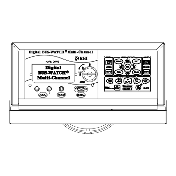
Page 24: Front Panel
Call REI Technical Support for special instructions on this topic at 1-877-726-4617. Front Panel The user controls the functions of the Digital BUS-WATCH® IV with the buttons on the front panel. (See Figure 16) Front Panel Keypad... -
Page 25: Menu System
The menu system allows the user to set and save the system operating parameters. Connect a monitor to the Digital BUS-WATCH® IV using the front jacks labeled AUDIO and VIDEO. To activate the menu system, press the MENU button. The first screen that appears is the Main Menu. -
Page 26: Main Menu Screen
Used to program this specific unit's Vehicle ID # or description. CALIBRATION Allows the user to calibrate the speedometer and voltmeter functions. CAPTURE IMAGE Used when downloading digital images to a PC via the serial port. Radio Engineering Industries, Inc. 640333 Rev 0 -- 1/1/2006... -
Page 27: System Information Screen
• SPEEDO FACTOR: A number used by the microprocessor control software to • calibrate the internal speedometer that uses the transmission pulse outputs. RECORD HOURS: Total number of hours the Digital BUS-WATCH® IV unit has • recorded video footage. •... -
Page 28: Set Time/Date Screen
Use the arrow buttons to step through the month, day, and year. The weekday is set automatically. Repeat this with the hours, minutes, and seconds. AM/PM is set automatically. Reference: Figure 19. Time/Date Menu Screen Shot Figure 19 Radio Engineering Industries, Inc. 640333 Rev 0 -- 1/1/2006... - Page 29 2007 as shown in Figure 21. When the DST Mode is set to ‘CUSTOM’, the Daylight Saving Time triggers can be changed to any of the first, second, third, fourth, or last week of any month, not overlapping. 2006 DST Trigger Screen Shot Figure 20 Radio Engineering Industries, Inc. 640333 Rev 0 -- 1/1/2006...
-
Page 30: Audio Control Menus
Figure 21 Audio Control Menus The REI Digital BUS-WATCH® IV has 2 audio channels labels as 1 & 2, or white and red, respectively. The Channel Selection Menu allows users to configure which cameras are recorded on which channels, and the Playback Volume Menu allows the user to change the volume level of either output channel. -
Page 31: Audio Channel Selection Menu
Playback Volume Menu Use the up and down arrow buttons and the SEL button to change the volume output levels. The REI Digital BUS-WATCH® IV always records audio at the maximum record level on both channels. Use this setting for control of the Playback Output Levels. -
Page 32: Set Vehicle Id Screen
GPS output when valid GPS data is present. When valid GPS data is not present, as in long tunnels or around many very tall buildings, the transmission pulse data will display if connected and calibrated properly. Radio Engineering Industries, Inc. 640333 Rev 0 -- 1/1/2006... -
Page 33: Speedometer Calibration Screen
Speedometer Calibration Screen Because speedometers can vary greatly among bus manufacturers, the Digital BUS-WATCH® IV has the ability to calibrate its own speedometer to that of the bus. Follow this procedure to calibrate the speedometer: Drive the bus at a known and constant speed, such as 30 mph. -
Page 34: Speedometer Signal Levels Screen
Speedometer Signal Levels Screen Considering the wide variety of speedometer pulse signal levels from the various types of transmissions, the Digital Bus-Watch® IV System allows users to manually set the speedometer input filter circuitry to best match the vehicle output signal. -
Page 35: Center On-Screen Display
Use the arrow buttons to center the four 'X's in the screen. Pressing MENU resets this setting to the factory defaults. When finished, press EXIT to save the settings. Center OSD Page Screen Shot Figure 30 Radio Engineering Industries, Inc. 640333 Rev 0 -- 1/1/2006... -
Page 36: Adjust Width
See Figure 32. Note: With all MENU functions, you must have a video monitor connected to the VIDEO OUT jack on the Digital BUS-WATCH® IV. Live video images cannot be transferred directly to PC through the serial cable. That function is accomplished through the Digital BUS-WATCH®... - Page 37 Digital BUS-WATCH ® The procedure to download an image from the Digital BUS-WATCH® IV is as follows. Connect the serial cable from the PC to the jack on the front of the Digital BUS- • WATCH® IV. On the PC, open and run the REI Viewer software. (The software must be •...
- Page 38 If you want to download more images, you can either use the control panel on the Digital BUS-WATCH® IV or use the other buttons on the virtual control panel. Before you can move to the next image, however, you must PAUSE the video.
- Page 39 • When you are finished downloading images, press the EXIT button on the front panel of the Digital BUS-WATCH® IV. This switches the unit back into the MENU mode, and transfers control from the PC back to unit's control panel.
-
Page 40: On Screen Display Options
512008 cable; and whether or not the inputs from the 512008 cable are active high, active low, or any given mixture. Reference Figure 36: On-Screen Display Options Screen Shot Figure 36 Radio Engineering Industries, Inc. 640333 Rev 0 -- 1/1/2006... -
Page 41: Main Display Options
Bus Speedometer (MPH, KMH, or KTS). • • HARDWARE VERSION Differentiates Newer DVRs with a “v4”. • SENSOR DATA Warning lights, brakes, stop-arm, etc. IGNITION Disabled, Temporary, & Continuous Display. • Radio Engineering Industries, Inc. 640333 Rev 0 -- 1/1/2006... -
Page 42: Gps Display Options
Character Display Options allow you to change what wire colors create which characters are displayed on the screen. Reference: Figure 39. Radio Engineering Industries, Inc. 640333 Rev 0 -- 1/1/2006... -
Page 43: Sensor Display Options
Reference: Figures 40-42. Vehicle Sensor Display Options Screen Shot – School Bus Settings Figure 40 Radio Engineering Industries, Inc. 640333 Rev 0 -- 1/1/2006... - Page 44 Digital BUS-WATCH ® Vehicle Sensor Display Options Screen Shot – Transit Settings Figure 41 Vehicle Sensor Display Options Screen Shot – Custom Settings Figure 42 Radio Engineering Industries, Inc. 640333 Rev 0 -- 1/1/2006...
-
Page 45: Sensor Level Options
(DATE), the first record recorded video in any given hour (HOUR), or search by the alarm triggered events that were set up in the ALARM RECORDING OPTOINS screen (ALARM). Reference: Figure 44. Radio Engineering Industries, Inc. 640333 Rev 0 -- 1/1/2006... -
Page 46: Recording Options
This item takes you to another screen that allows you to access the options that relate to the recording quality. Use the arrows and SEL buttons to select the items as desired. The recording quality of the Digital BUS-WATCH® IV has three independent settings: REC MODE, REC FPS, and REC QUALITY. Reference: Figure 45. - Page 47 7776 4320 3888 2160 1944 1080 High 5184 2880 2592 1440 1296 Super 2592 1440 1296 Field Frame Field Frame Field Frame Field Frame Quality Basic Normal High Super Figure 46 Radio Engineering Industries, Inc. 640333 Rev 0 -- 1/1/2006...
-
Page 48: Overwrite Menu
OFF DELAY: Can be set to any number from 0 to 99. This is the number of minutes the Digital BUS-WATCH® IV will to record after the System Switch has been turned off. The default for this setting is 0 minutes. Note: This function only works in MANUAL Record Mode (see below). -
Page 49: Alarm Record Menu
Pressing the SEL button when the cursor is set to a particular line toggles the asterisk on or off. Reference: Figure 49. (Shown using the Transit Character Display Option) Radio Engineering Industries, Inc. 640333 Rev 0 -- 1/1/2006... -
Page 50: Alarm Record Options
Digital BUS-WATCH ® Alarm Trigger Options Screen Shot Figure 49 Alarm Record Options Alarm Record Options Screen Shot Figure 50 Radio Engineering Industries, Inc. 640333 Rev 0 -- 1/1/2006... -
Page 51: Audible Alarm Options
Pressing the SEL button when the cursor is set to a particular line toggles the asterisk on or off. Reference: Figure 51. Audible Alarm Options Screen Shot Figure 51 Radio Engineering Industries, Inc. 640333 Rev 0 -- 1/1/2006... - Page 52 4 video signals. Overwriting Video First-In, First-Out The Digital BUS-WATCH® IV DVR records video in a FIFO (First-In First-Out) manner. The oldest video is overwritten by the newest video. When the DVR is...
-
Page 53: Set Record Timers Screen
"MF" setting, which causes the timer to work on every weekday, Monday through Friday. All timers should be set up in advance. Any timer that is not used should be disabled by setting it to ‘No’ (N). Radio Engineering Industries, Inc. 640333 Rev 0 -- 1/1/2006... - Page 54 Reader®. • The REI Viewer Software, which is used when downloading images to a PC from the Digital BUS-WATCH® IV. • Product Pictures, Specifications, & Diagrams. Downloading images to a PC via the serial cable requires the REI Viewer Software. This software must be installed on the PC before attempting to download any images.
-
Page 55: Digital Bus-Watch® Iv Systems Related Part Numbers
Digital BUS-WATCH ® Digital BUS-WATCH® IV Systems Related Part Numbers Digital Video Recording & Playback Units ΙV 710000 Digital Bus-Watch® , Under-seat Mount ΙV 710000FM Digital Bus-Watch® , Floor Mount ΙV 710005 Digital Bus-Watch® Viewing Station Hard Drives 710020 DBW4 120 GB Hard Drive Module... - Page 56 Digital BUS-WATCH ® Digital Bus-Watch® ΙΙ to Digital Bus-Watch® ΙV Transfer Harnesses 512015 Bus-Watch® Vehicle Sensor Options Transfer Harness, BW to DBW4 512017 Bus-Watch® Power Transfer Harness, BW to DBW4 512018 Bus-Watch® External Record Signal Transfer Cable, DBW2 to DBW4 512026 Bus-Watch®...
-
Page 57: Typical Camera Lens Viewing Angles
Digital BUS-WATCH ® Typical Camera Lens Viewing Angles Figure 53 Figure 54 Radio Engineering Industries, Inc. 640333 Rev 0 -- 1/1/2006... -
Page 58: Specifications
Playback Scanning Speed Up to 650x Video Output 1.1Vp-p, 75 Ohm unbalanced Audio Output -5dBm, 600 Ohm unbalanced Digital Compression Proprietary Wavelet Search Features Search by: Date, Hour, & Alarm Events Radio Engineering Industries, Inc. 640333 Rev 0 -- 1/1/2006...
Need help?
Do you have a question about the BUS-WATCH and is the answer not in the manual?
Questions and answers