
Subscribe to Our Youtube Channel
Related Manuals for Radio Engineering Industries Digital BUS-WATCH SD40


Summary of Contents for Radio Engineering Industries Digital BUS-WATCH SD40
- Page 1 Digital BUS-WATCH ® Digital ® BUS-WATCH SD40 710292 Hardware User Manual Hardware Installation Manual Page 1 of 72 Radio Engineering Industries, Inc. 640434 -- Rev 0 -- 9/30/2011...
-
Page 2: Table Of Contents
Vehicle Sensor Options Harness Vehicle Connections ............23 On-Screen Information with Vehicle Sensor Options Harness ..........24 Accelerometer Module Harness................. 25 Physical Mounting Requirements ................26 Page 2 of 72 Radio Engineering Industries, Inc. 640434 -- Rev 0 -- 9/30/2011... - Page 3 Play Back ..........................64 Video Search ......................65 DVR Firmware Upgrading .................... 71 Front Panel USB Firmware Upgrade ................71 Ethernet Firmware Upgrade ..................71 Specifications ........................72 Page 3 of 72 Radio Engineering Industries, Inc. 640434 -- Rev 0 -- 9/30/2011...
-
Page 4: List Of Figures
® Digital BUS-WATCH SD40 List of Figures Figure 1: SD40 Expanded System Overview ..............8 Figure 2: Front Panel Layout ....................9 Figure 3: Rear Panel Layout ..................... 10 Figure 4: DVR Remote Control ..................11 Figure 5: Remote Control Button Description ..............12 Figure 6: Remote Control Navigation Arrows.............. - Page 5 Figure 56: Files List Page Extra Function ................ 67 Figure 57: Event Search Function..................68 Figure 58: Event List Page ....................69 Figure 59: Event List Page Extra ..................70 Page 5 of 72 Radio Engineering Industries, Inc. 640434 -- Rev 0 -- 9/30/2011...
-
Page 6: Introduction
The SD40 is a cost effective, fanless, embedded mobile DVR solution supporting up to 4 camera inputs. This system features a unique compact rugged design engineered to meet the demands of harsh mobile environments. The SD40 mobile DVR features the latest technologies including H.264/MPEG-4 Advanced Video Compression, dual streaming technology, and all solid state construction. - Page 7 ● External GPS antenna module for embedded digital information of GPS location, speed, heading, and time ● External 3-axis inertia sensor for embedded digital information or trigger of video-matched motion events for accident reconstruction Page 7 of 72 Radio Engineering Industries, Inc. 640434 -- Rev 0 -- 9/30/2011...
-
Page 8: System Overview
802.11G VIDEO MONITOR MONITOR WIRELESS BRIDGE KIT (OPT) 710163 12V SW 750252 SD40 BRIDGE KIT GROUND POWER CABLE (COMES w/832101) Figure 1: SD40 Expanded System Overview Page 8 of 72 Radio Engineering Industries, Inc. 640434 -- Rev 0 -- 9/30/2011... -
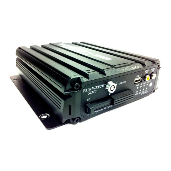
Page 9: Front And Back Panels
USB 2.0 CABLE CONNECTION LED STATUS INDICATORS, (8 INDICATORS) REMOTE I.R. SENSOR AUDIO OUTPUT CONNECTOR VIDEO OUTPUT CONNECTOR 7 SD CARD DOOR LOCK Figure 2: Front Panel Layout Page 9 of 72 Radio Engineering Industries, Inc. 640434 -- Rev 0 -- 9/30/2011... -
Page 10: Figure 3: Rear Panel Layout
AUDIO OUTPUT CONNECTION VIDEO OUTPUT CONNECTION ETHERNET CABLE CONNECTION CAMERA INPUTS (CAM 1-4 ) SENSORS (VEHICLE SENSOR CABLE CONNECTION) TRIGGER (ALARM/PANIC CABLE CONNECTION) Figure 3: Rear Panel Layout Page 10 of 72 Radio Engineering Industries, Inc. 640434 -- Rev 0 -- 9/30/2011... -
Page 11: Remote Control
® Digital BUS-WATCH SD40 Remote Control REMOTE Figure 4: DVR Remote Control Page 11 of 72 Radio Engineering Industries, Inc. 640434 -- Rev 0 -- 9/30/2011... -
Page 12: Figure 5: Remote Control Button Description
Press ENTER to select and EXIT to return. NEXT and PREV is also used to increase or decrease volume. Figure 6: Remote Control Navigation Arrows Page 12 of 72 Radio Engineering Industries, Inc. 640434 -- Rev 0 -- 9/30/2011... -
Page 13: Figure 7: Remote Control Numeric Input Keys
Use the numbers to input values in the system setup screen or switch through the channels in live and playback modes. Figure 7: Remote Control Numeric Input Keys Page 13 of 72 Radio Engineering Industries, Inc. 640434 -- Rev 0 -- 9/30/2011... -
Page 14: Initial Set Up
Gently remove the SD card from the slot. Note: The Digital BUS-WATCH® SD40 will not function properly if the SD card key is in the unlocked or off positions. If there is no SD card present in the slot but the key is in the locked and on position, the Digital BUS-WATCH®... -
Page 15: Figure 8: Removable Hard Drive Module Loading And Unloading
Unlock door Slide door open BUS-WATCH UNLOCK to access Card slot Use REI Approved SD Card Only Figure 8: Removable Hard Drive Module Loading and Unloading Page 15 of 72 Radio Engineering Industries, Inc. 640434 -- Rev 0 -- 9/30/2011... -
Page 16: Sd Card Record Times
3848 1154 2309 4618 1319 2639 5278 1480 2960 5950 1649 5920 6597 1847 3694 7389 7389 hours = 307 days of constant 24 hour recording Page 16 of 72 Radio Engineering Industries, Inc. 640434 -- Rev 0 -- 9/30/2011... -
Page 17: Long Term Storage
DVR to avoid draining the vehicle battery. The DVR internal clock will hold time and date for up to 10 years sitting on a shelf, and the daylight saving time functions will kick in upon re-initialization when power is applied. Page 17 of 72 Radio Engineering Industries, Inc. 640434 -- Rev 0 -- 9/30/2011... -
Page 18: Installation
The white wire (labeled 12V Battery) connects directly to the positive terminal of the battery. The white wire should be fused at 10 Amps see Figure 9. Page 18 of 72 Radio Engineering Industries, Inc. 640434 -- Rev 0 -- 9/30/2011... -
Page 19: Figure 9: System Wiring - Power And Camera Cables
BUS-WATCH DVR, SD40 TO BATTERY VIA IGN SWITCH 512359 SD40 DVR POWER CABLE 16-1/2 FT. TO BATTERY (UNSWITCHED) Note: White wire fused @ 7A (1-6 Cameras), 10A for more cameras; Red wire fused @ 1A. Figure 9: System Wiring – Power and Camera Cables Page 19 of 72 Radio Engineering Industries, Inc. -
Page 20: External Record Indicator / Event Mark Button Harness
POWER 12V OUT 710292 BUS-WATCH DVR, SD40 Figure 10: External Record Indicator / Event Mark Button Harness Connection The optional Digital BUS-WATCH® external record indicator / event mark button harnesses come in 2 different types of switches, both in 2 different lengths. The 2 types of switches are OEM and aftermarket. -
Page 21: Gps Antenna Module Harness
® Digital BUS-WATCH SD40 GPS Antenna Module Harness 710292 BUS-WATCH DVR, SD40 TRIGGER SENSORS CAM 1 CAM 2 CAM 3 CAM 4 ETHERNET REAR VIEW POWER 12V OUT 710214 GPS RECEIVER Figure 11: GPS Antenna Module Harness Connection The optional Digital BUS-WATCH® GPS antenna module harness plugs into the back of the DVR as shown in Figure 11 above. -
Page 22: Vehicle Sensor Options Harness
SENSOR INPUT 7 BLUE FRONT DOOR AUX 1 VIEW POWER 12V OUT 710292 BUS-WATCH DVR, SD40 SENSOR INPUT 8 VIOLET REAR DOOR AUX 2 REFER TO SPEEDOMETER HARNESS SECTION OF MANUAL Figure 12: Vehicle Sensor Options Harness Connection The BUS-WATCH® Vehicle Sensor Options Harness connects to various locations in the vehicle to provide on-screen information regarding vehicle performance. -
Page 23: Speedometer Harness Wiring Instructions
BLACK RED WARNING LAMP BROWN YELLOW WARNING LAMP LEFT TURN SIGNAL ORANGE RIGHT TURN SIGNAL YELLOW STOP ARM GREEN BRAKES BLUE FRONT DOOR VIOLET REAR DOOR Page 23 of 72 Radio Engineering Industries, Inc. 640434 -- Rev 0 -- 9/30/2011... -
Page 24: On-Screen Information With Vehicle Sensor Options Harness
LEFT TURN SIGNAL On RIGHT TURN SIGNAL On FRONT DOOR OPEN REAR DOOR OPEN SPEEDOMETER XX MPH (SEE NOTE 1) NOTE: The XXs represent the vehicle speed (i.e. 35). Page 24 of 72 Radio Engineering Industries, Inc. 640434 -- Rev 0 -- 9/30/2011... -
Page 25: Accelerometer Module Harness
® Digital BUS-WATCH SD40 Accelerometer Module Harness 710292 BUS-WATCH DVR, SD40 TRIGGER SENSORS CAM 1 CAM 2 CAM 3 CAM 4 ETHERNET REAR VIEW POWER 12V OUT 710143 ACCELEROMETER MODULE Figure 13: Accelerometer Module Harness Connection The optional external Accelerometer, or Inertia Sensor, must be hard mounted to the vehicle floor, frame, or some other non-dampened part of the vehicle. -
Page 26: Physical Mounting Requirements
DVR cannot be tampered with. Front View 2.28 in. 8.00 in. 7.5 in. 6.77 in. Rear View 5.51 in. 7.93 in. Figure 16: DVR Dimensions Page 26 of 72 Radio Engineering Industries, Inc. 640434 -- Rev 0 -- 9/30/2011... -
Page 27: Security Cover Mounting
Slot Opening Front cover Figure 17: Security Cover Mounting IMPORTANT: Check local, state, and federal guidelines as to modification of the existing structures within the vehicle. Page 27 of 72 Radio Engineering Industries, Inc. 640434 -- Rev 0 -- 9/30/2011... -
Page 28: Camera Placement
The Digital BUS-WATCH® camera shown in Figure 18 above is mounted to the center of the front header panel. Page 28 of 72 Radio Engineering Industries, Inc. 640434 -- Rev 0 -- 9/30/2011... -
Page 29: Figure 19: Potential Single And Two Camera Placement Options
® Digital BUS-WATCH SD40 Figure 19: Potential Single and Two Camera Placement Options Page 29 of 72 Radio Engineering Industries, Inc. 640434 -- Rev 0 -- 9/30/2011... -
Page 30: Figure 20: Potential Multiple Camera Placement Options
® Digital BUS-WATCH SD40 4 CAMERAS 4 CAMERAS INTERIOR EXTERIOR Figure 20: Potential Multiple Camera Placement Options Page 30 of 72 Radio Engineering Industries, Inc. 640434 -- Rev 0 -- 9/30/2011... -
Page 31: Typical Camera Lens Viewing Angles
® Digital BUS-WATCH SD40 Typical Camera Lens Viewing Angles Figure 21: 4mm Lens Angles Page 31 of 72 Radio Engineering Industries, Inc. 640434 -- Rev 0 -- 9/30/2011... -
Page 32: Figure 22: 8Mm Lens Angles
® Digital BUS-WATCH SD40 Figure 22: 8mm Lens Angles Page 32 of 72 Radio Engineering Industries, Inc. 640434 -- Rev 0 -- 9/30/2011... -
Page 33: Recording & Playback
OFF DELAY option is enabled, the Digital BUS-WATCH® will continue to record for the prescribed number of minutes. When the off-delay expires, the camera and Digital BUS-WATCH® shut off. Page 33 of 72 Radio Engineering Industries, Inc. 640434 -- Rev 0 -- 9/30/2011... -
Page 34: Playback Options
PC Network Connection Using the REI RMS PC Software, the user can access the files by connecting the computer to the DVR Front Panel Ethernet port, as shown in Figure 23 below. 710292 710277 BUS-WATCH DVR, SD40 COMPUTER TRIGGER SENSORS CAM 1... -
Page 35: Menu Configuration
All of the data associated with the video is digitally embedded into the video frames, creating a proprietary format that requires REI PC Software to decode and display. Page 35 of 72 Radio Engineering Industries, Inc. 640434 -- Rev 0 -- 9/30/2011... -
Page 36: Main Menu Page
Video Setup is where the recording, live, and OSD settings are. Input Setup is where the event, alarm and audible settings are. Network is where the Ethernet, Wi-Fi, and 3G settings are. Page 36 of 72 Radio Engineering Industries, Inc. 640434 -- Rev 0 -- 9/30/2011... -
Page 37: Setup Menu
Figure 26: System Setup The System section of the System Setup Sub-Menu is subdivided into four subcategories, Device Info, Time Date, Operating Mode, and Utility Menu. Page 37 of 72 Radio Engineering Industries, Inc. 640434 -- Rev 0 -- 9/30/2011... -
Page 38: Figure 27: Device Info
DEVICE-ID is generated automatically based on Organization and Vehicle ID and cannot be changed by the user. FIRMWARE VER. shows the firmware version the DVR currently has. Page 38 of 72 Radio Engineering Industries, Inc. 640434 -- Rev 0 -- 9/30/2011... -
Page 39: Figure 28: Device History
User can reset each individual record or select Reset All to reset all of them. Figure 28: Device History Page 39 of 72 Radio Engineering Industries, Inc. 640434 -- Rev 0 -- 9/30/2011... -
Page 40: Figure 29: System - Time/Date
GMT and needs to be offset for your time zone for proper automatic time synchronization. SYNC SOURCE allows the user to use a time synchronization system, either GPS, or NTP (Network Time Server), or None. Page 40 of 72 Radio Engineering Industries, Inc. 640434 -- Rev 0 -- 9/30/2011... -
Page 41: Figure 30: Custom Dst Triggers
Figure 30: Custom DST Triggers Page 41 of 72 Radio Engineering Industries, Inc. 640434 -- Rev 0 -- 9/30/2011... -
Page 42: Figure 31: Operating Mode
BOTH: DVR starts recording by schedule and when ignition is on at the same time. EITHER: DVR starts recording by schedule or when ignition is on. Page 42 of 72 Radio Engineering Industries, Inc. 640434 -- Rev 0 -- 9/30/2011... -
Page 43: Figure 32: Schedule Menu
DVR. When this setting is set to No, the user must manually delete files off the SD card, or format the card for more record time. Page 43 of 72 Radio Engineering Industries, Inc. 640434 -- Rev 0 -- 9/30/2011... -
Page 44: Figure 33: System - Utility Menu
Use the drop-down menu to select which media to format. Page 44 of 72 Radio Engineering Industries, Inc. 640434 -- Rev 0 -- 9/30/2011... -
Page 45: Figure 34: System - Password Protection
The Admin password allows the user to gain full access to all the menus, as if there were no password protection. Page 45 of 72 Radio Engineering Industries, Inc. 640434 -- Rev 0 -- 9/30/2011... -
Page 46: Video Setup
Video Setup Figure 35: Video Setup The Video Setup section of the menu is subdivided into 3 main categories, Record Settings, Live Settings, and OSD Settings. Page 46 of 72 Radio Engineering Industries, Inc. 640434 -- Rev 0 -- 9/30/2011... -
Page 47: Figure 36: Camera - Record Settings
Allows channel to be seen in Live View when set to ON, disables when set to OFF. AUDIO: Select ON or OFF for independent audio recording for each channel. Page 47 of 72 Radio Engineering Industries, Inc. 640434 -- Rev 0 -- 9/30/2011... -
Page 48: Figure 37: Custom Record Settings
CAPACITY: Resolution – CIF Frame rate – 8 FPS Alarm frame rate – 30 Quality – 4 CUSTOM: Custom record setting for each camera. Figure 37: Custom Record Settings Page 48 of 72 Radio Engineering Industries, Inc. 640434 -- Rev 0 -- 9/30/2011... -
Page 49: Figure 38: Sub-Streaming
DVR opens up sub-streaming page when entering live settings by default, highlight Custom button and press enter to switch to live video settings page. Page 49 of 72 Radio Engineering Industries, Inc. 640434 -- Rev 0 -- 9/30/2011... -
Page 50: Figure 39: System - Live Video Settings
QUALITY: Video Quality (1 - 8) Kbps: Video Bandwidth (16 - 2000) SUB-STREAM VIDEO TRANSMISSION PRIORITY: FRAME RATE (smoother video playback), VIDEO QUALITY (better video quality). Page 50 of 72 Radio Engineering Industries, Inc. 640434 -- Rev 0 -- 9/30/2011... -
Page 51: Figure 40: Osd Settings
SENSOR INPUT: The sensor input from the vehicle. ACCEL DATA: Acceleration data from the accelerometer. TEMPERATURE: Temperature of the device. FIRMWARE VER.: Device firmware version. GPS DATA: GPS coordinates from the GPS module. Page 51 of 72 Radio Engineering Industries, Inc. 640434 -- Rev 0 -- 9/30/2011... -
Page 52: Input Setup
The Input Setup allows the user to customize the name that shows up on the OSD when the sensor is activated, to calibrate speed signal and accelerometer, set the alarm settings, and adjust audible settings. Page 52 of 72 Radio Engineering Industries, Inc. 640434 -- Rev 0 -- 9/30/2011... -
Page 53: Figure 42: Sensor Input
N.C if button is normally closed. ALARM: Set to ON if triggering an alarm event is required when sensor is activated. DOWNLOAD: Allows the user to set auto-download settings. Page 53 of 72 Radio Engineering Industries, Inc. 640434 -- Rev 0 -- 9/30/2011... -
Page 54: Figure 43: Auto-Download Settings
5 is from priority one to five. DOWNLOAD ONLY PROTECTED ALARM VIDEO: When set to ON, user can only download protected alarm videos from the DVR. Page 54 of 72 Radio Engineering Industries, Inc. 640434 -- Rev 0 -- 9/30/2011... -
Page 55: Figure 44: Accelerometer Threshold
ACCEL THRESHOLD X/Y/Z: The minimum value to trigger an alarm event. X/Y/Z ALARM: When set to ON, if the sensor readings reach the threshold values, the DVR stores an accelerometer event. Page 55 of 72 Radio Engineering Industries, Inc. 640434 -- Rev 0 -- 9/30/2011... -
Page 56: Figure 45: Temperature Threshold
HIGH/LOW TEMP THRESHOLD: The highest/lowest temperature before triggering an alarm event. SPEED: The speed setup page allows the user to set speed source, calibrate speed sensor, and set speed limit. Page 56 of 72 Radio Engineering Industries, Inc. 640434 -- Rev 0 -- 9/30/2011... -
Page 57: Figure 46: Speed Threshold
SPD SENSITIVITY: Speed sensitivity affects the rate of read out change. Set to LOW for slower rate and HIGH for higher rate. Page 57 of 72 Radio Engineering Industries, Inc. 640434 -- Rev 0 -- 9/30/2011... -
Page 58: Figure 47: Alarm Settings
Record SETTING. When set to I FRAME, the DVR will record at one frame per second to take less space of the SD card. Page 58 of 72 Radio Engineering Industries, Inc. 640434 -- Rev 0 -- 9/30/2011... -
Page 59: Figure 48: Audible Settings
ALARM CONDITION: When set to ON, if there is an alarm occurring, the DVR will produce an audible alert. Also, the alarm LED on the DVR‟s front panel will illuminate. Page 59 of 72 Radio Engineering Industries, Inc. 640434 -- Rev 0 -- 9/30/2011... -
Page 60: Network
The Network menu contains three categories: Ethernet, Wi-Fi, and 3G. It gives the user the options to access DVR through wired or wireless network using varies type of devices. Page 60 of 72 Radio Engineering Industries, Inc. 640434 -- Rev 0 -- 9/30/2011... -
Page 61: Figure 50: Ethernet Settings
CLIENT PORT: This is the port where the user can access DVR‟s client function. WEB PORT: This is the port where the user can access DVR‟s web function. Page 61 of 72 Radio Engineering Industries, Inc. 640434 -- Rev 0 -- 9/30/2011... -
Page 62: Figure 51: Wi-Fi Settings
IP address in order to have access to the DVR. The last number must be set up independently on each DVR. Page 62 of 72 Radio Engineering Industries, Inc. 640434 -- Rev 0 -- 9/30/2011... - Page 63 DVR supports WEP and WPA security. Choose the one that the network is set up to and enter password using the remote. 3G Network Page 63 of 72 Radio Engineering Industries, Inc. 640434 -- Rev 0 -- 9/30/2011...
-
Page 64: Play Back
USERNAME: Username for the network. PASSWORD: Password for the network. ACCESS NUMBER: Please check this setting with network provider Play Back Figure 53: Play Back Function Page 64 of 72 Radio Engineering Industries, Inc. 640434 -- Rev 0 -- 9/30/2011... -
Page 65: Video Search
FILE TYPE: file type allows the user to choose between displaying all the days with videos or only the days that contain alarm events. DATE: enter specific date to search videos on that day. Page 65 of 72 Radio Engineering Industries, Inc. 640434 -- Rev 0 -- 9/30/2011... -
Page 66: Figure 55: Files List Page
CH: Channel number shows which channel this video is from. RES: Resolution of the video. FR: Frame rate of the video. TIME: When the video started and ended recording. Page 66 of 72 Radio Engineering Industries, Inc. 640434 -- Rev 0 -- 9/30/2011... -
Page 67: Figure 56: Files List Page Extra Function
SD card or even export videos to external USB storage. Page 67 of 72 Radio Engineering Industries, Inc. 640434 -- Rev 0 -- 9/30/2011... -
Page 68: Figure 57: Event Search Function
If the date only contains normal events, it will be green. If there is an alarm event, the date will be red. Page 68 of 72 Radio Engineering Industries, Inc. 640434 -- Rev 0 -- 9/30/2011... -
Page 69: Figure 58: Event List Page
SEL: Select videos by highlighting the box in the front and press enter on the remote to mark the videos. EVENT: The type of the event. DATE: The date of the event. TIME: Time when the event happened. Page 69 of 72 Radio Engineering Industries, Inc. 640434 -- Rev 0 -- 9/30/2011... -
Page 70: Figure 59: Event List Page Extra
EX LOG: To export event log, select EX LOG button and press enter on the remote control (external USB storage needs to be plugged in first). Page 70 of 72 Radio Engineering Industries, Inc. 640434 -- Rev 0 -- 9/30/2011... -
Page 71: Dvr Firmware Upgrading
EXIT Button: Exit Event List page. DVR Firmware Upgrading Due to improvements in technology and the availability of new features, the SD40 DVR comes with the ability to have the firmware (DVR operating system) be easily upgraded in the field. There are several ways this can be done: through the Ethernet connection or through the front panel USB connection. -
Page 72: Specifications
■ Vibration: 1.0G, 5 ~ 500Hz (Operating), 5.0G, 5 ~ 500Hz (Storage / Transit) ■ Power Requirement: 12VDC @ 2A / 24VDC @ 1A ■ Power Consumption: 24W Maximum ■ EMC and Safety: CE, FCC Page 72 of 72 Radio Engineering Industries, Inc. 640434 -- Rev 0 -- 9/30/2011...
Need help?
Do you have a question about the Digital BUS-WATCH SD40 and is the answer not in the manual?
Questions and answers