NETGEAR M4100 Series Hardware Installation Manual
M4100 series managed switch
Hide thumbs
Also See for M4100 Series:
- Reference manual (578 pages) ,
- User manual (446 pages) ,
- Hardware installation manual (29 pages)

Related Manuals for NETGEAR M4100 Series


Summary of Contents for NETGEAR M4100 Series
-
Page 1: Managed Switch
Managed Switch H ardware In stallation Guide Models: M4100 Series 350 East Plumeria Drive San Jose, CA 95134 November 2013 202-11217-02 v1.0... -
Page 2: Revision History
NETGEAR, the NETGEAR logo, ProSafe, Smart Wizard, and Auto Uplink are trademarks or registered trademarks of NETGEAR, Inc. Microsoft, Windows, Windows NT, and Vista are registered trademarks of Microsoft Corporation. Other brand and product names are registered trademarks or trademarks of their respective holders. -
Page 3: Table Of Contents
Contents Chapter 1 Introduction Front Panels and LEDs ........4 Rear Panels . -
Page 4: Chapter 1 Introduction
This guide describes hardware installation and basic troubleshooting for these managed switches. These switches can be freestanding, wall mounted, or rack mounted in a wiring closet or an equipment room. For information about features for each product, visit the NETGEAR website at http://www.netgear.com. Front Panels and LEDs The following figures show the front panels of the ProSafe 4100 series managed switches. - Page 5 NETGEAR Managed Switch LEDs USB port SFP ports RJ-45 ports Reset button -26G Figure 1. M4100 front panel Power RJ45 SPD/Link/ACT mode: Green = 1G Yellow = 10/100M Blink = ACT Reset USB SFP SPD/Link/ACT mode: Green = Link at 1G...
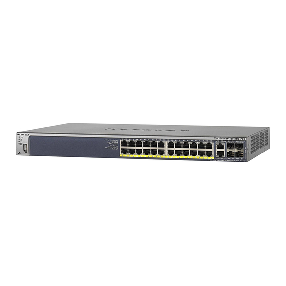
- Page 6 NETGEAR Managed Switch LEDs USB port Reset button POE ports SFP ports RJ-45 ports Figure 5. M4100-26G-POE front panel LEDs USB port POE ports Reset button SFP ports RJ45 ports Figure 6. M4100-50G-POE+ front panel LEDs USB port SFP ports...
- Page 7 NETGEAR Managed Switch M4100-24G-POE+ SPD/Link/ACT PoE (Max 30W per port): SFP SPD/Link/ACT mode Off = No PD Power Green = PoE Powered Green = Link at 1G Yellow = PoE Fault Yellow = Link at 100M Blink = ACT RJ45 SPD/Link/ACT mode:...
- Page 8 NETGEAR Managed Switch Table 1. LED descriptions Description Power Solid green: Internal power supply operating normally and supplying power to the switch. Solid yellow: The system is in boot-up stage. Blinking yellow: Power module is present but has failed. Off: Power is disconnected.
-
Page 9: Rear Panels
NETGEAR Managed Switch Table 1. LED descriptions (Continued) Description Link/ACT Off: No link is established on the port. (RJ45 port) Solid green: A valid link is established on the port. Blinking green: Packets transmission or reception is occurring on the port. -
Page 10: Safety Instructions
NETGEAR Managed Switch Console switch Lock Power adapter Console connector ports Figure 14. M4100-D10-POE and M4100-D12G rear panels Lock AC power Console connector power supply port connector Figure 15. M4100-12GF, 24G-POE+, 12G-POE+ rear panel Console AC power Lock port connector Figure 16. - Page 11 NETGEAR Managed Switch Opening or removing covers that are marked with the triangular symbol with a lightning bolt might expose you to electrical shock. Only a trained service technician should service components inside these compartments. • If any of the following conditions occur, unplug the product from the electrical outlet and replace the part or contact your trained service provider: The power cable, extension cable, or plug is damaged.
- Page 12 NETGEAR Managed Switch • Observe extension cable and power strip ratings. Make sure that the total ampere rating of all products plugged into the extension cable or power strip does not exceed 80 percent of the ampere ratings limit for the extension cable or power strip.
-
Page 13: Chapter 2 Hardware Installation
Hardware Installation This chapter explains how to install the hardware for the managed switches. Package Contents Each switch is packed and shipped separately. The package contains the following items: • Managed stackable switch with preinstalled software • Power cord • Rubber footpads for tabletop installation •... -
Page 14: Unpack The Hardware
Make sure that all items are present. For more information, see Package Contents page 13. Note: If any item is missing or damaged, contact your local NETGEAR reseller for replacement. Inspect the products and accessories for damage. Report any damage immediately. -
Page 15: Select A Location
NETGEAR Managed Switch For more information, see Connect to Power and Check the LEDs on page 20. Select a Location The switch can be mounted in a standard 19-inch (48.26-centimeter) rack, wall mounted, or left freestanding (placed on a tabletop). -
Page 16: Install The Switch
NETGEAR Managed Switch Install the Switch You can install the switch on a flat surface or in a standard 19-inch rack. Install the Switch on a Flat Surface The switch ships with four self-adhesive rubber footpads. Stick one rubber footpad on each of the four concave spaces on the bottom of the switch. - Page 17 NETGEAR Managed Switch Use the provided Phillips head screws to fasten the brackets to the sides of the switch. Mounting bracket Tighten the screws with a No. 1 Phillips screwdriver to secure each bracket. Align the bracket and rack holes. Use two pan-head screws with nylon washers to fasten each bracket to the rack.
- Page 18 NETGEAR Managed Switch Install the Switch on a Wall (M4100-D12G, M4100-D10-PoE, and M4100-D12G-POE+ Only) If you install the switch on a wall in the vertical position, be sure to orient the switch as shown in the following figure. The switch should be mounted so that the ports face up or down.
-
Page 19: Install The M4100-D12G Or M4100-D10-Poe Using Magnets
NETGEAR Managed Switch Install the M4100-D12G or M4100-D10-PoE Using Magnets If you use the magnets (included) to install the M4100-D12G or M4100-D10-PoE switch to a vertical metal surface, the maximum height above the floor is 75 centimeters (29.5 inches). Be sure to orient the switch as shown in the following figure. Exhaust air should come out the side of the switch case. -
Page 20: Check The Installation
NETGEAR Managed Switch Check the Installation Before you apply power, perform the following checks: Inspect the equipment thoroughly. Verify that all cables are installed correctly. Check cable routing to ensure that cables are not damaged and will not create a safety hazard. -
Page 21: Sfp Modules
NETGEAR Managed Switch • If the POST fails, the Power LED blinks yellow. Note: If the PD LED on the front panel of the M4100-D12G and M4100-D12G-POE+ blinks green, port 1 is connected to a IEEE802.3af PoE device. Check the PoE device specification to make sure that it supports IEEE802.3at. -
Page 22: Connect Equipment To The Switch
NETGEAR Managed Switch Connect Equipment to the Switch You can connect devices, a Gigabit Ethernet module, and/or a console to the switch. RJ-45 Ports The switch uses Auto Uplink technology, which enables you to attach devices using either straight-through or crossover cables. Use a Category 5 (Cat 5) unshielded twisted-pair (UTP) cable terminated with an RJ-45 connector. - Page 23 NETGEAR Managed Switch Connect the other end of the cable to a workstation or terminal. If you attached a workstation, start a terminal emulation program. • Microsoft Windows users can use HyperTerminal if it comes with the Windows operating system. If it does not, you need to install another third-party terminal emulator such as Tera Term.
-
Page 24: Chapter 3 Troubleshooting
Troubleshooting Troubleshooting Chart The following table lists symptoms, causes, and solutions to possible problems. Table 3. Troubleshooting chart Problem Cause Solution Power LED is off. No power is received. Check the power cord connections for the switch at the switch and the connected device. Make sure that all cables used are correct and comply with Ethernet specifications. -
Page 25: Additional Troubleshooting Suggestions
You can verify the integrity of the switch by resetting the switch. To reset the switch, use the Tools > Reset command, or remove AC power from the switch and then reapply AC power. If the problem continues, contact NETGEAR technical support. •... -
Page 26: Appendix A Technical Specifications
Technical Specifications Table 4. M4100-26G, 50G, 26G-POE, 50G-POE+, and D12G Gigabit switch physical specifications Specification M4100-26G M4100-50G M4100-26G-POE M4100-50G-POE+ M4100-D12G (GSM7224v2h2) (GSM7248v2h2) (GSM7226LP) (GSM7248P) (GSM5212) Interface 26 RJ-45 ports for 50 RJ-45 ports, 26 RJ-45 ports for 50 RJ-45 ports for 12 RJ-45 ports for 10/100/1000 Mbps 10/100/1000 Mbps... - Page 27 NETGEAR Managed Switch Table 5. M4100-24G-POE+, D12G-POE+, 12G-POE+, 12GF Gigabit switch physical specification Specification M4100-24G-POE+ M4100-D12G-POE+ M4100-12G-POE+ M4100-12GF (GSM7224P) (GSM5212P) (GSM7212P) (GSM7212F) Interface 24 RJ-45 ports for 12 RJ-45 ports for 12 RJ-45 ports for 12 RJ-45 ports for 10/100/1000 Mbps...
- Page 28 NETGEAR Managed Switch Table 6. Fast Ethernet switches physical specifications Fast Ethernet Switches M4100-26-POE M4100-50-POE M4100-D10-POE (FSM7226P) (FSM7250P) (FSM5210P) Interface 24 RJ-45 ports for 48 RJ-45 ports for 8 RJ-45 ports for 10/100 Mbps 10/100 Mbps 10/100 Mbps (AutoUplink on all RJ-45...
- Page 29 NETGEAR Managed Switch Table 7. Technical specifications Feature Description IEEE Network Protocol • 802.3i 10BASE-T and Standards • 802.3u 100BASE-TX compatibility • 802.3z 1000BASE-X • 802.3ab 1000BASE-T • 802.3az EEE • 802.3x flow control • 802.3af power over Ethernet • 802.3at power over Ethernet Switch management •...
- Page 30 NETGEAR Managed Switch Table 7. Technical specifications (Continued) Feature Description Security • Radius • TACACS+ • 802.1x • MAC filter • Port security • Protected port • Private group • Storm control • DHCP snooping • IP source guard • Dynamic ARP inspection •...
-
Page 31: Appendix B Default Configuration Settings
Default Configuration Settings Table 8. M4100 Series switch default settings Feature Default Setting Port speed Autonegotiation Port duplex Autonegotiation Flow control (half duplex) Enabled Flow control (full duplex) Disabled Broadcast storm control Enabled Gigabit port type Auto detect Management IP... - Page 32 NETGEAR Managed Switch Table 8. M4100 Series switch default settings (Continued) Feature Default Setting GMRP Disabled IP routing Disabled MAC address aging 300 seconds SNMP community public (read-only access), private (read/write access) DHCP Server Disabled VLAN Ingress filtering Enabled IP multicast filtering Disabled 802.1x...
-
Page 33: Appendix C Notification Of Compliance
Communications du Canada. EN 55 022 Declaration of Conformance This is to certify that the NETGEAR ProSafe® 4100 series managed switches are shielded against the generation of radio interference in accordance with the application of Council Directive 89/336/EEC, Article 4a. Conformity is... - Page 34 EN 55 022 and EN 55 024 Statements This is to certify that the NETGEAR ProSafe® 4100 series managed switches are shielded against the generation of radio interference in accordance with the application of Council Directive 89/336/EEC, Article 4a. Conformity is declared by the application of EN 55 022 Class A (CISPR 22) and EN 55 024.
Need help?
Do you have a question about the M4100 Series and is the answer not in the manual?
Questions and answers