
Subscribe to Our Youtube Channel
Related Manuals for Generac Power Systems QT 5.4L


Summary of Contents for Generac Power Systems QT 5.4L
-
Page 1: Serial Number
Serial Number STANDBY GENERATOR OWNER'S MANUAL 0F3607 Part A new standard of reliability This manual should remain with the unit. 5.4L 100kW Models 08/05 Rev. Cover008... -
Page 2: Table Of Contents
SECTION SAFETY RULES ... 1-1 INTRODUCTION ...1-3 Read this Manual Thoroughly ...1-3 Operation and Maintenance ...1-3 How to Obtain Service ...1-3 IDENTIFICATION RECORD ...2-1 Data Label ...2-1 EQUIPMENT DESCRIPTION ...3-1 Equipment Description ...3-1 Engine Oil Recommendations ...3-1 Coolant Recommendations...3-1 ENGINE PROTECTIVE DEVICES ...4-1 Coolant Temperature Sensing ...4-1 Low Coolant Level ...4-1 Oil Pressure Sensing ...4-1... -
Page 3: Safety Rules
SAVE THESE INSTRUCTIONS – The manufacturer suggests that these rules for safe operation be copied and posted in potential hazard areas. Safety should be stressed to all operators, potential operators, and service and repair technicians for this equipment. WARNING: The engine exhaust from this product contains chemicals known to the state... -
Page 4: Fire Hazards
• Before performing any maintenance on the gen- erator, disconnect its battery cables to prevent accidental start-up. Disconnect the cable from the battery post indicated by a NEGATIVE, NEG or (–) first. Reconnect that cable last. • Never use the generator or any of its parts as a step. -
Page 5: Introduction
DATA LABEL affixed to the unit. AUTHORIZED SERVICE DEALER LOCATION SERVICE DEALER, please call this number: To locate the nearest AUTHORIZED 1-800-333-1322 or locate us on the web at: www.generac.com 08/05 Rev. Safety... -
Page 6: Identification Record
ALTERNATOR SUBTRANSIENT REACTANCE ALTERNATOR TRANSIENT REACTANCE CLASS ROTOR STATOR WINDING INSULATION AT 25°C AMBIENT GENERAC POWER SYSTEMS, INC. WAUKESHA, WI NOTE: For actual information related to this particular model, please refer to the Manual Drawing Listing located at the end of this manual, or to the data label affixed to the unit. -
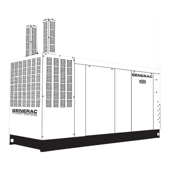
Page 7: Equipment Description
EQUIPMENT DESCRIPTION This equipment is a revolving field, alternating cur- rent generator set. It is powered by a gaseous fueled engine operating at 1800 rpm for 4-pole direct drive units, 3600 rpm for 2-pole direct drive units and 2300 - 3000 rpm for quiet drive gear units. See the Specifications section for exact numbers. -
Page 8: Engine Protective Devices
ENGINE PROTECTIVE DEVICES The standby generator may be required to operate for long periods of time without an operator on hand to monitor such engine conditions as coolant tempera- ture, oil pressure or rpm. For that reason, the engine has several devices designed to protect it against potentially damaging conditions by automatically shutting down the unit when the oil pressure is too low, the coolant temperature is too high, the coolant... -
Page 9: Fuel Systems
FUEL SYSTEM FUEL REQUIREMENTS The standby generator may be equipped with one of the following fuel systems: • Natural gas fuel system • Propane vapor (PV) fuel system • Liquid propane (LP) fuel system The Manual Drawing Listing that is affixed to the unit includes the “Identification Code,”... -
Page 10: Specifications
Generator Locked Rotor KVA Available @ Voltage Dip of 35% Single-phase or 208 3-phase ... 190 KVA 480V, 3-phase ... 225 KVA ENGINE Make ... Generac Model ... V-type Cylinders and Arrangement ... 8 Displacement ... 5.4 Liter Bore ... 3.55 in. -
Page 11: Cold Weather Kit
GROUND ONLY AT GENERATOR BOX COLD WEATHER KIT For cold climates, optional cold weather kit (part num- ber 0F6148A) is recommended. The kit includes: • Battery Warmer • 4” Junction Box with hardware • Thermostat; 20 deg “ON”, 40 deg “OFF” •... -
Page 12: 5.4L & 6.8L Ignition Description
5.4L & 6.8L IGNITION DESCRIPTION This single-fire Ignition is intended to operate with a 10-cylinder, 6.8L engine and an 8-cylinder, 5.4L engine. The 6.8L engine uses a 40-1 crank sensor, a mag- pickup CAM sensor and individual coil-on-plug coils for each spark-plug. The 5.4L engine uses a 36-1 crank sensor, a mag- pick-up CAM sensor and individual coil-on-plug coils for each spark-plug. -
Page 13: General Information
GENERATOR AC LEAD CONNECTIONS See “Voltage Codes”. This generator may be rated at any one of three voltages, either single-phase or three-phase. The electrical wires in the unit’s AC con- nection (lower) panel should be installed according to the number of leads and the voltage/phase required for the application. -
Page 14: Installation
INSTALLATION Refer to the separate “Installation Guide QT Product Line” supplied with the unit. PREPARATION BEFORE START-UP The instructions in this section assume that the standby generator has been properly installed, ser- viced, tested, adjusted and otherwise prepared for use by a competent, qualified installation contractor. Be sure to read the “Safety Rules”, as well as all other safety information in this manual, before attempting to operate this (and related) equipment. -
Page 15: Start-Up Checklist
Authorized Service Dealer. The installer should complete the form and disseminate copies as follows: • White copy: Mail to Generac Warranty Department, P .O. Box 340, 211 Murphy Dr., Eagle, WI 53119- 2062. • Pink Copy: For service file of installing dealer. -
Page 16: Operation
GENERATOR CONTROL AND OPERATION Refer to the appropriate control panel operator’s manual for this unit. OPERATING UNIT WITH MANUAL TRANSFER SWITCH If the generator was installed in conjunction with a transfer switch capable of manual operation only, the following procedure applies. A manually operated transfer switch is one that will not provide automatic start-up and does not include an intelligence circuit. -
Page 17: Maintenance Performed By Authorized Service Facilities
MAINTENANCE PERFORMED BY AUTHORIZED SERVICE FACILITIES Before working on the generator, ensure the fol- lowing: • The AUTO/OFF/MANUAL switch is in the OFF position. • The 15A fuse has been removed from the con- trol box. • The 120VAC supply to the battery charger is switched OFF . -
Page 18: Engine Coolant
ENGINE COOLANT Check coolant level in coolant recovery bottle. See the “Specifications” section. • Add recommended coolant mixture as necessary. • Periodically remove radiator pressure cap to make sure the coolant recovery system is functioning properly. Coolant should be at bottom of radiator filler neck. -
Page 19: Changing The Engine Air Cleaner
7. Start engine and check for oil leaks. Figure 10.2 - Oil Filter Oil Filter CHANGING THE ENGINE AIR CLEANER To replace the engine air cleaner, (part number 0A4637), remove the air cleaner cover and replace the air filter making sure it is positioned properly before reattaching the cover. -
Page 20: Battery
Finally, have the insulation resistance of stator and rotor windings checked. If insulation resistances are excessively low, the generator may require drying. BATTERY All lead-acid storage batteries discharge when not in use. Refer to specific instructions and warnings that accompany the battery. If such information is not available, observe the following precautions when handling a battery: •... -
Page 21: Service Schedule
SERVICE SCHEDULE 30 KW - 150 KW STANDBY GAS ENGINE DRIVEN GENERATOR SETS The following is a recommended maintenance schedule for standby gas engine driven generator sets from 30kW to 150 kW in size. The established intervals in the schedule are the maximum recommended when the unit is used in an average service application. - Page 22 Maintenance Level 1 Tasks Recom- mended Comp. to be done Comp. to be done to be done (Date- monthly/ Initials) 10 hrs. 1. Disable the unit from operating per the first page warning. 2. Check the engine oil level. Adjust as necessary.
- Page 23 Maintenance Level 1 Tasks Recom- mended Comp. to be done Comp. to be done to be done (Date- monthly/ Initials) 10 hrs. 10. Check the engine accessory drive belts and fan coupling device if equipped for correct tension, wear, weather cracking, and damage.
- Page 24 Maintenance Level 1 Tasks Recom- mended Comp. to be done Comp. to be done to be done (Date- monthly/ Initials) 10 hrs. 18. Start and exercise the unit at full rated load (use a load bank if the site load is not enough) for at least 2 hours looking for leaks,...
-
Page 25: Troubleshooting
TROUBLESHOOTING GUIDE PROBLEM CAUSE Engine won’t crank. Engine cranks but won't start Engine starts hard, runs rough. Engine starts then shuts down. AUTO/OFF/MANUAL Switch at OFF, engine continues to run No AC output from generator. *Contact the nearest Authorized Dealer for assistance. Standby Generator Sets Troubleshooting 1. - Page 26 Standby Generator Sets Notes...
- Page 27 Standby Generator Sets Notes...
- Page 29 0F9952 ASSY ROTOR 2390 80KB3 CPL 0F3417 ASSY ROTOR 390 2P 100K BRSHLS 0F2984 ASSY ROTOR 390 2P 150K BRSHLS 0F9949 ASSY STATOR 80KW 1PH 2P BRSHLS 0F3418 ASSY STATOR 390 2P 100K BRSHLS 0F2985 ASSY STATOR 390 2P 150K BRSHLS UL 0F9950 STATOR 2390 80 GB3 CPL 0F9951...
- Page 31 0F2885 PANEL CB CONN BOX 0F2883 STAND RH CONTROL 0F9637 (4) STAND RH CONTROL, TWO HOLE (FOR 5.4L 100KW & 4.6L 80KW 1PHASE) 0F3685 STAND LH CONTROL C5 GRBX 023484N BUSHING SNAP SB-2.5-31 023484N BUSHING SNAP SB-2.5-31 (FOR 5.4L 100KW & 4.6L 80KW 1PHASE) 086961 INTERFACE 1PH 240V...
- Page 33 UL CIRCUIT BREAKER (225AF) 0F4173 COVER CB C5 225AF 065469 DECAL DANGER HIGH VOLTAGE 0F4165$ CIRCUIT BREAKERS 200A FRAME 0F4186 COVER CB DISH 225AF 036261 RIVET POP .125 X .275 SS 053640 SCREW RHM #8-32 X 3-1/4 038150 WASHER FLAT #8 ZINC 022264 WASHER LOCK #8-M4 022471...
- Page 35 0F2885 PANEL CB CONN BOX 0G0171 STAND, RH CONTROL CPL C5 0G0171A STAND RH CONTROL CPL C5 2 HOLE 0G0172 STAND, LH CONTROL CPL C5 023484N BUSHING SNAP SB-2.5-31 0F4677 ASSY PCB INTERFACE 1PH 240V 067617030A INTERFACE 3PHS 416/480V 067617030B INTERFACE 3PHS 208/240V 043180 WASHER FLAT M4...
- Page 37 0F2687 WELDMENT RADIATOR SUPPORT150 0F2611 RADIATOR 680 X 680 X 70 CPL 0F5254 V-BELT 31/64" X 62-3/8" 0F5253 V-BELT 31/64" X 61-3/8" (5.4L 100KW ONLY) 0F7077 V-BELT 1/2" X 63-3/8" (6.8L 100 130KW) 046526 WASHER LOCK M10 051756 SCREW HHC M10-1.5 X 20 G8.8 0C2454 SCREW THF M6-1 X 16 N WA Z/JS 052250...
- Page 39 0F3099 MTG BASE CP 5.4L 100KW DD 065852 SPRING CLIP HOLDER .37-.62 052252 DAMPENER VIBRATION 052257 SPACER .49 X .62 X 1.87 PWDR/ZINC 052259 WASHER FLAT M12 055597 SCREW HHC M12-1.75 X 85 G8.8 052251A DAMPENER VIBRATION 50 WHITE 052860 NUT LOCKING M12-1.75 0F2895 SUPPORT ENG 5.4L LH/RH 6.8L RH...
- Page 41 0F3408 TRAY BATTERY 0F3411 STRAP BATTERY RETAINMENT 058208 BATT 12VDC 24F 625 022131 WASHER FLAT 3/8-M10 ZINC 050331A BATT POST COVER RED + 050331 BATT POST COVER BLK - 038805U CABLE BATT BLK #1 X 18.00 038804U CABLE BATT RED #1 X 28.00 045771 NUT HEX M8-1.25 G8 YEL CHR 022129...
- Page 43 COMPONENTS INCLUDED IN 0F1826E 0F1823 ENCL H CONTROL PANEL 0F1824 COVER CONTROL PANEL 0F2606 HINGE CONTINUOUS H-PNL 036261 RIVET POP .125 X .275 SS 0F5763 ASSY PROGRAMMED PM H-100 0F1732 DECAL FUSES LOCATED INSIDE 0E9764 RAIL SNAPTRACK PCB HOLDER BULK (12” LG) 0F1725C ASSY PCB 2AMP 12V UL BATT CHGR 0F1958...
- Page 45 0F2807C PIPE EXH MAN R/H 6.8L G/B CPL (6.8L C5) 0F2807E PIPE EXH MAN R/H 5.4L G/B & 2P (5.4L C5) 0F9207 PIPE EXH MANIFOLD 4.6L RH 0F2807B PIPE EXH MAN L/H 6.8L G/B CPL (6.8L C5) 0F2807D PIPE EXH MAN L/H 5.4L G/B & 2P (5.4L C5) 0F9208 PIPE EXH MANIFOLD 4.6L LH 0F4505...
- Page 47 0D2513D AIR CLNR BTM PLT W/CPLR 8.1L 0F5419 ELEMENT AIR FILTER 0F4268 TOP PLATE VENTURI 0F4270A HOLD DOWN AIR CLEANER PLATED 0F6977 PLATE AIR CLEAN TOP 5.4L/6.8L 037561 NUT WING 1/4-20 NYLK 047411 SCREW HHC M6-1.0 X 16 G8.8 022097 WASHER LOCK M6-1/4 049811 WASHER FLAT M6...
- Page 49 0F3883 TUBE HEATER WATER 0F1960 ENGINE 5.4L FORD 0F2842 IGNITION COIL ASSY FORD 0F2843 GASKET THERMOSTAT HOUSING FORD 5 ** 0D5419 OIL FILTER FORD V-10 ENGINE 0F2849 TUBE OIL LEVEL INDICATOR FORD 0D3488G BELT SERPENTINE 65.0" (1800 RPM) 0D3488L SERPENTINE BELT (66.0") (2650 RPM) 0D3488K SERPENTINE BELT (68.3") (3600 RPM) 057795A...
- Page 51 0D9913 SCREW SHC M8-1.25 X 35 SS 0E9747 STARTER 12 VOLT 0F3514 SPACER FLEXPLATE 5.4L/6.8L (1800 RPM ONLY) 0F3903C FLEX PLATE 2 POLE 5.4L & 6.8L (1800 RPM UNITS ONLY) 0F3903C FLEX PLATE 2 POLE 5.4L & 6.8L (3600 RPM UNITS ONLY) 0F2776A BRACKET, SIGNAL CONDITIONER 0D5417...
- Page 53 049721 SCREW HHC M6-1.0 X 35 G8.8 BLK 065908 SUPPORT NAT GAS SOLENOID 0F6261G REGULATOR ASSM 5.4L 80KW NG 0F6261C REGULATOR ASSM 5.4L 100KW NG 0F6261D REGULATOR ASSM 6.8L 100KW NG 052617 SCREW HHC M12-1.75 X 20 G8.8 022304 WASHER FLAT 1/2 ZINC 022129 WASHER LOCK M8-5/16 045773...
- Page 55 033212 SCREW HHC 5/16-18 X 1-1/4 G5 065908 SUPPORT NAT GAS SOLENOID 0F6261H REGULATOR ASSM 5.4L 80KW LPV (5.4L 80KW) 0F6261J REGULATOR ASSM 5.4L 100KW LPV (5.4L 100KW) 0F6261K REGULATOR ASSM 6.8L 100KW LPG (6.8L 100KW) 0F6261L REGULATOR ASSM 6.8L 130KW LPV (6.8L 130KW) 0F6261M REGULATOR ASSM 6.8L 150KW LPV (6.8L 150KW) 052617...
- Page 57 (2) 1 0F5873 REAR WRAP C5 (2) 2 0F5868 DOOR C5 (2) 3 0F5872 CENTER SUPPORT C5 (2) 4 0F5871 DISCHARGE DUCT LH & RH SIDE C5 (2) 5 0F5869 FRONT CORNERS C5 (2) 6 0F5870 DISCHARGE CENTER DUCT C5 (2) 7 0F5867 ROOF C5 ALUM...
- Page 76 • A Generac Power Systems, Inc. Transfer Switch is highly recommended to be used in conjunction with the genset. If a Non - Generac Power Systems, Inc. Transfer Switch is substituted for use and directly causes damage to the genset, no warranty coverage shall apply.
Need help?
Do you have a question about the QT 5.4L and is the answer not in the manual?
Questions and answers