Table of Contents
Advertisement
Quick Links
S5U13U00P00C100 USB 2.0 Adapter
Board User Manual
Document Number: I00Z-G-018-01
Status: Revision 1.0
Issue Date: 2007/03/20
© SEIKO EPSON CORPORATION 2007. All Rights Reserved.
Information in this document is subject to change without notice. You may download and use this document, but only for your own use in
evaluating Seiko Epson/EPSON products. You may not modify the document. Epson Research and Development, Inc. disclaims any
representation that the contents of this document are accurate or current. The Programs/Technologies described in this document may contain
material protected under U.S. and/or International Patent laws.
EPSON is a registered trademark of Seiko Epson Corporation. All other trademarks are the property of their respective owners.
Revision 1.0
Advertisement
Table of Contents

Related Manuals for Epson S5U13U00P00C100


Summary of Contents for Epson S5U13U00P00C100
- Page 1 The Programs/Technologies described in this document may contain material protected under U.S. and/or International Patent laws. EPSON is a registered trademark of Seiko Epson Corporation. All other trademarks are the property of their respective owners. Revision 1.0...
- Page 2 Page 2 Epson Research and Development Vancouver Design Center S5U13U00P00C100 USB 2.0 Adapter Board User Manual I00Z-G-018-01 Issue Date: 2007/03/20 Revision 1.0...
-
Page 3: Table Of Contents
Ordering Information ......20 S5U13U00P00C100 USB 2.0 Adapter Board User Manual Issue Date: 2007/03/20 I00Z-G-018-01 Revision 1.0... - Page 4 Page 4 Epson Research and Development Vancouver Design Center S5U13U00P00C100 USB 2.0 Adapter Board User Manual I00Z-G-018-01 Issue Date: 2007/03/20 Revision 1.0...
-
Page 5: Introduction
Board. This board was designed as an evaluation interface for connecting Epson LCD Controllers Evaluation Boards to a computer using USB connection. This user manual is updated as appropriate. Please check the Epson Research and Devel- opment Website at www.erd.epson.com for the latest revision of this document before beginning any development. -
Page 6: Features
• Header Signals for connecting Epson LCD Controllers Evaluation Boards • 5V input power (separate power input, not from USB) • 3.3V power supply available for Epson LCD Controllers Evaluation Boards • LED power indicator • Bidirectional voltage translation buffers for the host bus signals, to interface to wide range of host bus voltages S5U13U00P00C100 USB 2.0 Adapter Board User Manual... -
Page 7: Installation
S5U13U00P00C100 board with headers P1 and P2 on the Epson LCD Controllers evalu- ation board and connect the two boards. After the boards are connected, 5V power may be connected to S5U13U00P00C100. Once the power is applied, the USB cable from the PC may be connected to S5U13U00P00C100 board. 3.1 USB driver S5U13U00P00C100 USB Adapter board needs the Epson USB driver, S1D13XXXUSB, installed on the host computer. -
Page 8: Technical Description
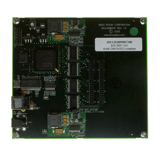
JP1 - Host Bus Voltage JP1 selects the voltage level of the host bus on connectors P1 and P2. When the jumper is at position 1-2, the voltage level is HIOVDD provided by the Epson LCD Controllers evaluation boards (recommended setting). -
Page 9: Status Indicators
Figure 4-1: Jumper JP1 Location 4.3 Status Indicators S5U13U00P00C100 has a green LED “5V PWR” to indicate when 5V power is present. The board outputs 2 signals on connector P1 to indicate if the board is working and if the board has completed enumeration on USB.These signals are 3.3 volt, regardless of the host... -
Page 10: Parts List
C75,C76,C77,C78,C79, C80,C81,C117,C118, Yageo America C0402 C119,C120,C121,C122, 04022R102K9B20D C123,C124,C125,C126, C127,C128,C129,C130, C131,C132,C133,C134, C135,C136,C177,C189, C193,C201 C112,C113,C114,C115, Panasonic - ECG C116,C167,C168,C169, C0402 ECJ-0EB0J105M C170,C171 Kemet C181,C199 4.7uF 10V T C3528 T491B475K010AS S5U13U00P00C100 USB 2.0 Adapter Board User Manual I00Z-G-018-01 Issue Date: 2007/03/20 Revision 1.0... - Page 11 PWR1 Power Jack 2BSM PJ-002A-SMT Sullins Electronics P1,P2 SOCKET_20x2 HDR2X20 PPWN102AFCN International Rectifier Q1,Q2 IRF8910 SOIC-8 IRF8910 R1,R2,R107,R117 2.7K R0603 R0603 R4,R5,R7,R8,R12,R13, R15,R16,R17,R18,R19, R20,R21,R22,R80,R81, R0402 R82,R83,R84,R85,R86, R87,R88,R96,R97,R98, S5U13U00P00C100 USB 2.0 Adapter Board User Manual Issue Date: 2007/03/20 I00Z-G-018-01 Revision 1.0...
- Page 12 BG456 package; Insight/Memec Cypress CY7C68001- CY7C6800 CY7C68001-56PVXC 56PVC 1SSOP56 Cypress direct 24MHz CB3_OSC CB3LV-3C-24M0000-T Intergrated Circuit Systems SSOP_28_ ICS525-01 ICS525-01RI Insight, All-American, Nu Horizons U5,U6,U7,U8 74AVCB164245 SN74AVCB164245GR S5U13U00P00C100 USB 2.0 Adapter Board User Manual I00Z-G-018-01 Issue Date: 2007/03/20 Revision 1.0...
- Page 13 SOT-223 MIC37100-1.8BS 1.8BS Micrel direct STMicroelectronics U11,U13 L6910 SO-16 L6910TR Micrel MIC37100- SOT-223 MIC37100-2.5BS 2.5BS Micrel direct Texas Instruments TPS3801K33D SOT323-5 TPS3801K33DCKR IC 2.93V SUPPLY MON SOT-323-5 S5U13U00P00C100 USB 2.0 Adapter Board User Manual Issue Date: 2007/03/20 I00Z-G-018-01 Revision 1.0...
-
Page 14: Schematics
Page 14 Epson Research and Development Vancouver Design Center 6 Schematics Figure 6-1: S1D13U00P00C100 Schematics (1 of 4) S5U13U00P00C100 USB 2.0 Adapter Board User Manual I00Z-G-018-01 Issue Date: 2007/03/20 Revision 1.0... - Page 15 Page 15 Vancouver Design Center VCCA VCCA VCCA VCCA VCCB VCCB VCCB VCCB VCCA VCCA VCCA VCCA VCCB VCCB VCCB VCCB Figure 6-2: S1D13U00P00C100 Schematics (2 of 4) S5U13U00P00C100 USB 2.0 Adapter Board User Manual Issue Date: 2007/03/20 I00Z-G-018-01 Revision 1.0...
- Page 16 Page 16 Epson Research and Development Vancouver Design Center Figure 6-3: S1D13U00P00C100 Schematics (3 of 4) S5U13U00P00C100 USB 2.0 Adapter Board User Manual I00Z-G-018-01 Issue Date: 2007/03/20 Revision 1.0...
- Page 17 Epson Research and Development Page 17 Vancouver Design Center BOOT BOOT OCSET OCSET COMP COMP Figure 6-4: S1D13U00P00C100 Schematics (4 of 4) S5U13U00P00C100 USB 2.0 Adapter Board User Manual Issue Date: 2007/03/20 I00Z-G-018-01 Revision 1.0...
-
Page 18: Pcb Layout
Page 18 Epson Research and Development Vancouver Design Center 7 PCB Layout Figure 7-1: S1D13U00P00C100 PCB Layout (Top) S5U13U00P00C100 USB 2.0 Adapter Board User Manual I00Z-G-018-01 Issue Date: 2007/03/20 Revision 1.0... - Page 19 Epson Research and Development Page 19 Vancouver Design Center Figure 7-2: S1D13U00P00C100 PCB Layout (Bottom) S5U13U00P00C100 USB 2.0 Adapter Board User Manual Issue Date: 2007/03/20 I00Z-G-018-01 Revision 1.0...
-
Page 20: Sales And Technical Support
Fax: (65) 6271-3182 http://www.epson.com.hk/ http://www.epson.com.sg/ 8.1 Ordering Information To order the S5U13U00P00C100 Evaluation Board, contact the Epson sales representative in your area and order part number S5U13U00P00C100. S5U13U00P00C100 USB 2.0 Adapter Board User Manual I00Z-G-018-01 Issue Date: 2007/03/20 Revision 1.0... - Page 21 Epson Research and Development Page 21 Vancouver Design Center Change Record I00Z-G-018-01 Revision 1.0 - Issued: March 20, 2007 • Generate this document S5U13U00P00C100 USB 2.0 Adapter Board User Manual Issue Date: 2007/03/20 I00Z-G-018-01 Revision 1.0...
Need help?
Do you have a question about the S5U13U00P00C100 and is the answer not in the manual?
Questions and answers