Table of Contents
Advertisement
Advertisement
Table of Contents

Related Manuals for Abit VT7


Summary of Contents for Abit VT7
- Page 1 Socket 478 System Board User’s Manual 4200-0387-02 Rev. 1.00...
- Page 2 Copyright and Warranty Notice The information in this document is subject to change without notice and does not represent a commitment on part of the vendor, who assumes no liability or responsibility for any errors that may appear in this manual. No warranty or representation, either expressed or implied, is made with respect to the quality, accuracy or fitness for any particular part of this document.
-
Page 3: Table Of Contents
VT7 快速安裝指引 ................... 2 VT7 のクイックインストールガイド ........... 4 VT7 Schnellinstallationsanleitung ............6 VT7 Guide d’Installation Rapide............8 Краткое руководство по установке VT7........... 10 Guida all’installazione veloce Scheda madre VT7 ......12 Chapter 1. Introduction ................1-1 1-1. Features & Specifications ................1-1 1-2. - Page 4 Appendix D. Install VIA USB 2.0 Driver .............D-1 Appendix E. Install Serial ATA RAID Driver............E-1 Appendix F. ABIT EQ (The Hardware Doctor Utility) ........F-1 Appendix G. FlashMenu (BIOS Update Utility) ..........G-1 Appendix H. Troubleshooting (Need Assistance?)..........H-1 Appendix I.
- Page 5 User’s Manual User’s Manual...
-
Page 6: Vt7 快速安裝指引
VT7 快速安裝指引 VT7 快速安裝指引 安裝處理器的散熱片以及風扇組件 (Zero Insertion Force, ZIF) ® ® Socket 478 Intel Pentium 4 CPU ® Pentium 4 Socket 478 Socket 478 ® 注意: Pentium 注意:... - Page 7 VT7 快速安裝指引 將主機板安裝到機殼上 安裝記憶體模組 DIMM DIMM DIMM DIMM DIMM DIMM DIMM DIMM DIMM DIMM 注意: 連接器、連接頭以及附加卡的安裝 SCSI 將電源供應器的電源線連接頭與主機板上的 ATX12V 電源接頭連接起來 ATX12V BIOS 的設定 BIOS User’s Manual...
-
Page 8: Vt7 のクイックインストールガイド
VT7 のクイックインストールガイド VT7 のクイックインストールガイド CPU ヒートシンクとファンアセンブリの取り付け ZIF ( ® ® ) Socket 478 Intel Pentium ® Pentium Socket 478 ® 注意:Pentium... - Page 9 VT7 のクイックインストールガイド 注意: マザーボードをシャーシに取り付ける RAM モジュールの取り付け DIMM 2. DIMM DIMM DIMM 5. DIMM 注意 : コネクタ、ヘッダ、スイッチおよびアダプタ SCSI 電源コネクタを ATX12V 電源コネクタに差し込む 出 ATX12V 奥 着 BIOS のセットアップ ハ ウ 了 BIOS Setup 移 User’s Manual...
-
Page 10: Vt7 Schnellinstallationsanleitung
VT7 Schnellinstallationsanleitung VT7 Schnellinstallationsanleitung Beziehen Sie sich bitte für detaillierte Informationen über diese Hauptplatine auf die vollständige Version des Benutzerbuchs. Diese Schnellinstallationsanleitung ist für erfahrene Systemaufbauer gedacht. Ist es Ihr erster Versuch ein Computersystem aufzubauen, dann empfehlen wir Ihnen zuerst das vollständige Benutzerhandbuch zu lesen oder einen Techniker zum Aufbauen des Systems zu Hilfe zu holen. - Page 11 VT7 Schnellinstallationsanleitung Achtung: Vergessen Sie nicht, die korrekte Busfrequenz und -Multiplikator für Ihren Prozessor einzustellen. Installieren der Hauptplatine im Gehäuse Nach der Installation des Prozessors können Sie anfangen die Hauptplatine im Computergehäuse zu befestigen. Die meisten Gehäuse haben eine Bodenplatte, auf der sich eine Reihe von Befestigungslöcher befinden, mit deren Hilfe Sie die Hauptplatine sicher verankern können und zugleich Kurzschlüsse...
-
Page 12: Vt7 Guide D'installation Rapide
VT7 Guide d’Installation Rapide VT7 Guide d’Installation Rapide Pour des informations relatives à cette carte mère plus détaillées, veuillez vous référer à notre version complète du manuel utilisateur. Ce guide d’installation rapide est créé pour les assembleurs système expérimentés. S’il s’agit de votre premier essai pour installer un ordinateur, nous vous suggérons de lire d’abord le manuel en version complète ou de demander l’aide d’un technicien pour vous aider à... - Page 13 VT7 Guide d’Installation Rapide Attention: N’oubliez pas de programmer la fréquence de bus correcte et le multiple pour votre processeur. Installer la Carte Mre dans le Châssis Une fois que vous aurez installé le processeur sur la carte mère, vous pourrez commencer à fixer la carte mère sur le châssis.
-
Page 14: Краткое Руководство По Установке Vt7
Краткое руководство по установке VT7 Краткое руководство по установке VT7 Более подробные сведения о материнской плате приведены в руководстве пользователя. Краткое руководство по установке предназначено для опытных специалистов. Если вы собираете компьютер впервые, ознакомьтесь сперва с руководством пользователя или попросите техника... - Page 15 Краткое руководство по установке VT7 Внимание: Установите соответствующие частоту и кратность шины процессора. Установка материнской платы в корпус После установки процессора на материнскую плату можно начинать установку материнской платы в корпус. Большая часть корпусов оборудована основанием, в котором проделаны монтажные отверстия, которые позволяют надежно закрепить материнскую плату и предотвратить...
-
Page 16: Guida All'installazione Veloce Scheda Madre Vt7
Guida all’installazione veloce Scheda madre VT7 Guida all’installazione veloce Scheda madre VT7 Per maggiori e dettagliate informazioni su questa scheda madre si prega di fare riferimento alla versione integrale del Manuale utente. Questa guida all’installazione veloce è intesa per costruttori esperi di sistemi. - Page 17 Guida all’installazione veloce Scheda madre VT7 Attenzione: Non dimenticare di impostare la corretta frequenza multipla e BUS per il processore. Installazione della scheda madre sul telaio Dopo avere installato il processore sulla scheda madre si può iniziare a fissare la scheda madre sul telaio.
-
Page 19: Chapter 1. Introduction
Introduction Chapter 1. Introduction 1-1. Features & Specifications 1. CPU • Supports Intel Pentium 4 Socket 478 processor with 800MHz, 533MHz, and 400MHz (for Northwood only) System Data Bus • Supports Intel Hyper-Threading Technology 2. Chipset • VIA PT880 + VT8237 •... - Page 20 • 1x AUDIO1 connector (Rear-Left / Rear-Right, Center/Subwoofer) • 1x AUDIO2 connector (Mic-In, Line-In, Front-Left/Front-Right) • 2x USB connectors • 2x USB connectors, 1x RJ-45 LAN connector 11. ABIT Engineered ™ • ABIT SoftMenu Technology ™ • ABIT TweakGuard ™...
-
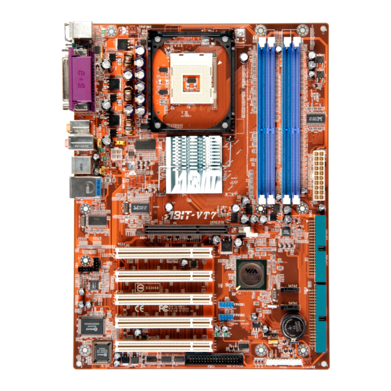
Page 21: Layout Diagram
Introduction 1-2. Layout Diagram User’s Manual... - Page 22 Chapter 1 Chapter 1...
-
Page 23: Chapter 2. Hardware Setup
Hardware Setup Chapter 2. Hardware Setup Before the Installation: Turn off the power supply switch (fully turn off the +5V standby power), or disconnect the power cord before installing or unplugging any connectors or add-on cards. Failing to do so may cause the motherboard components or add-on cards to malfunction or damaged. 2-1. -
Page 24: Install Pentium ® 4 Cpu And Heatsink Supporting-Base
Chapter 2 ® 2-2. Install Pentium 4 CPU and Heatsink Supporting-Base This motherboard provides a ZIF (Zero Insertion ® ® Force) Socket 478 to install Intel Pentium CPU. The CPU you bought should have a kit of heatsink and cooling fan along with. If that’s not ®... -
Page 25: Install System Memory
Hardware Setup 2-3. Install System Memory This motherboard provides four 184-pin DDR DIMM slots for Single/Dual Channel DDR 400/333/266 memory modules with memory expansion size up to 4GB. To reach the performance of Dual Channel DDR, the following rules must be obeyed: •... -
Page 26: Connectors, Headers And Switches
Chapter 2 2-4. Connectors, Headers and Switches Here we will show you all of the connectors, headers and switches, and how to connect them. Please read the entire section for necessary information before attempting to finish all the hardware installation inside the computer chassis. -
Page 27: Fan Connectors
Hardware Setup (2). FAN Connectors These 3-pin connectors each provide power to the cooling fans installed in your system. The CPU must be kept cool by using a powerful fan with heatsink. The system is capable of monitoring the speed of the CPU fan. •... -
Page 28: Cmos Memory Clearing Header
Chapter 2 (3). CMOS Memory Clearing Header This header uses a jumper cap to clear the CMOS memory. • Pin 1-2 shorted (default): Normal operation. • Pin 2-3 shorted: Clear CMOS memory. WARNING: Turn the power off first (including the +5V standby power) before clearing the CMOS memory. -
Page 29: Wake-Up Header
Hardware Setup (4). Wake-up Header These headers use a jumper cap to enable/disable the wake-up function. • PS2-PWR1: Pin 1-2 shorted (default): Disable wake-up function support at Keyboard/Mouse port. Pin 2-3 shorted: Enable wake-up function support at Keyboard/Mouse port • USB-PWR1: Pin 1-2 shorted (default): Disable wake-up function support at USB1 port. -
Page 30: Front Panel Switches & Indicators Headers
Chapter 2 (5). Front Panel Switches & Indicators Headers This header is used for connecting switches and LED indicators on the chassis front panel. Watch the power LED pin position and orientation. The mark “+” align to the pin in the figure below stands for positive polarity for the LED connection. -
Page 31: Additional Usb Port Headers
Hardware Setup (6). Additional USB Port Headers These headers each provide 2 additional USB 2.0 ports connection through an USB cable designed for USB 2.0 specifications. Pin Assignment Pin Assignment Data0 - Data1 - Data0 + Data1 + Ground Ground User’s Manual... -
Page 32: Internal Audio Connectors
2-10 Chapter 2 (7). Internal Audio Connectors These connectors connect to the audio output of internal CD-ROM drive or add-on card. (8). Accelerated Graphics Port Slot This slot supports an optional AGP graphics card up to AGP 8X mode. Please refer to our Web site for more information on graphics cards. -
Page 33: Floppy Disk Drive Connector
Hardware Setup 2-11 (9). Floppy Disk Drive Connector This connector supports two standard floppy disk drives via a 34-pin 34-conductor ribbon cable. Connecting the Floppy Disk Drive Cable: 1. Install one end of the ribbon cable into the FDC1 connector. The colored edge of the ribbon cable should be aligned with pin-1 of FDC1 connector. -
Page 34: Ide Connectors
2-12 Chapter 2 (10). IDE Connectors This motherboard provides two IDE ports to connect up to four IDE drives at Ultra ATA/100 mode by Ultra ATA/66 ribbon cables. Each cable has 40-pin 80-conductor and three connectors, providing two hard drives connection with motherboard. Connect the single end (blue connector) at the longer length of ribbon cable to the IDE port on motherboard, and the other two ends (gray and black connector) at the shorter length of the ribbon cable to the connectors on hard drives. -
Page 35: Serial Ata Connectors
Hardware Setup 2-13 (11). Serial ATA Connectors These connectors are provided to attach one Serial ATA device at each channel via Serial ATA cable. A RAID 0 or RAID 1 array is also available by software configuration. (12). System Management Bus Headers This header is reserved for system management bus (SM bus). -
Page 36: Status Indicator
2-14 Chapter 2 (13). Status Indicator • D18 (5VSB): This LED lights up when the power supply is connected with power source. -
Page 37: Back Panel Connectors
Hardware Setup 2-15 (14). Back Panel Connectors • Mouse: Connects to PS/2 mouse. • Keyboard: Connects to PS/2 keyboard. • LPT1: Connects to printer or other devices that support this communication protocol. • COM1: Connects to external modem, mouse or other devices that support this communication protocol. - Page 38 2-16 2-16 Chapter 2 Chapter 2...
-
Page 39: Chapter 3. Bios Setup
BIOS Setup Chapter 3. BIOS Setup This motherboard provides a programmable EEPROM that you can update the BIOS utility. The BIOS (Basic Input/Output System) is a program that deals with the basic level of communication between processor and peripherals. Use the BIOS Setup program only when installing motherboard, reconfiguring system, or prompted to “Run Setup”. -
Page 40: Softmenu Setup
Chapter 3 3-1. SoftMenu Setup The SoftMenu utility is ABIT’s exclusive and ultimate solution in programming the CPU operating speed. All the parameters regarding CPU FSB speed, multiplier factor, the AGP & PCI clock, and even the CPU core voltage are all available at your fingertips. - Page 41 BIOS Setup Multiplier Factor: This item sets the multiplier factor for the CPU you installed. NOTE: Some processors might have this multiplier factor locked, so there is no way to choose a higher multiplier factor. Estimated new CPU clock: This item displays the clock frequency sum up from the previous items [Ext. Clock] and [Multiplier Factor].
-
Page 42: Standard Cmos Features
Chapter 3 3-2. Standard CMOS Features Date (mm:dd:yy): This item sets the date you specify (usually the current date) in the format of [Month], [Date], and [Year]. Time (hh:mm:ss): This item sets the time you specify (usually the current time) in the format of [Hour], [Minute], and [Second]. - Page 43 BIOS Setup Access Mode: This item selects the mode to access your IDE devices. Leave this item to its default [Auto] setting to detect the access mode of your HDD automatically. Capacity: This item displays the approximate capacity of the disk drive. Usually the size is slightly greater than the size of a formatted disk given by a disk-checking program.
- Page 44 Chapter 3 [All Errors]: The system-boot will stop whenever the BIOS detect a non-fatal error. [No Errors]: The system-boot will not stop for any error detected. [All, But Keyboard]: The system-boot will stop for all errors except a keyboard error. [All, But Diskette]: The system-boot will stop for all errors except a diskette error.
-
Page 45: Advanced Bios Features
BIOS Setup 3-3. Advanced BIOS Features Hyper-Threading Technology This item is used to enable the functionality of the processor with Hyper-Threading Technology and will appear only when using such processor. The Hyper-Threading Technology helps your PC work more efficiently by maximizing processor resources and enabling a single processor to run two separate threads of software simultaneously, bringing forth greater performance and system responsiveness when running multiple applications at once. - Page 46 Chapter 3 Swap Floppy Drive: When set to [Enabled], and the system is booting from the floppy drive, the system will boot from drive B instead of the regular drive A. There must be two floppy drives connected in the system to use this function.
- Page 47 BIOS Setup NOTE: Set this option to [No] setting if there are adapters that cannot be automatically detected by the system and will cause malfunction. Intel OnScreen Branding: This item determines whether to display the “Intel Inside” logo or not at system boots up. User’s Manual...
-
Page 48: Advanced Chipset Features
3-10 Chapter 3 3-4. Advanced Chipset Features DRAM Clock/Drive Control: Click <Enter> key to enter its submenu: DRAM Timing: This item determines the timing method of the DRAM modules. [Manual]: This option allows you to select the best option in the following sub-items manually. [Auto By SPD]: This option allows the system to run the SPD (Serial Presence Detect) data structure stored in the DRAM module automatically. - Page 49 BIOS Setup 3-11 DRAM BUS Selection: This item determines the channel of DRAM modules from [Single Channel] or [Dual Channel]. The [Single Channel] option allows a standard 64-bit access rate. The [Dual Channel] option will have a double 128-bit access rate. Leave this item to its default [Auto] setting to have it selected automatically. NOTE: It is highly recommended to use the DRAMs of the identical brand name and specification for slots [DIMM1]+[DIMM3] or slots [DIMM2]+[DIMM4] in order to achieve a better performance.
- Page 50 3-12 Chapter 3 AGP Fast Write: This item determines the AGP Fast Write feature, a technology that allows the CPU to write directly to the graphics card without passing anything through the system memory so as to improve the AGP speed. Set to [Enabled] only when the installed AGP card supports the function.
- Page 51 BIOS Setup 3-13 Back to Advanced Chipset Features Setup Menu: System BIOS Cacheable: When set to [Enabled], accesses to the system BIOS ROM addressed at F0000H-FFFFFH are cached, provided that the cache controller is enabled. The larger the range of the Cache RAM, the higher the efficiency of the system will be.
-
Page 52: Integrated Peripherals
3-14 Chapter 3 3-5. Integrated Peripherals VIA OnChip IDE Device: Click <Enter> key to enter its submenu: SATA RAID ROM: This item allows you to use the boot ROM of onchip Serial ATA RAID to boot-up system. IDE Bus Master: This option enables or disables the IDE bus mastering capability under the DOS environment. - Page 53 BIOS Setup 3-15 Back to Integrated Peripherals Setup Menu: VIA OnChip PCI Device: Click <Enter> key to enter its submenu: OnChip Audio Controller: This option enables or disables the audio controller. OnChip LAN Controller: This option enables or disables the LAN controller. OnChip LAN Boot ROM: This item enables or disables the Boot ROM on LAN controller.
- Page 54 3-16 Chapter 3 Back to Integrated Peripherals Setup Menu: SuperIO Device: Click <Enter> key to enter its submenu: Onboard FDC Controller: This option enables or disables the onboard FDC controller. Onboard Serial Port 1: This item determines which I/O addresses the onboard Serial Port controller will access. [Auto]: The system automatically select an I/O address for the onboard Serial Port.
- Page 55 BIOS Setup 3-17 [ECP]: (Extended Capabilities Port) Allows bi-directional parallel port operation at a speed faster than the normal mode’s data transfer rate. [ECP+EPP]: Allows parallel port operation at ECP and EPP mode. EPP Mode Select: This item selects the EPP mode. ECP Mode Use DMA: This item selects the DMA channel of the parallel port.
-
Page 56: Power Management Setup
3-18 Chapter 3 3-6. Power Management Setup ACPI Suspend Type: This item selects the type of Suspend mode. [S1(PowerOn-Suspend)]: Enables the Power On Suspend function. [S3(Suspend-To-RAM)]: Enables the Suspend to RAM function. Power Button Function: This item selects the method of powering off your system: [Delay 4 Sec.]: Pushing the power button for more than 4 seconds will power off the system. - Page 57 BIOS Setup 3-19 IRQ/Event Activity Detect: Click <Enter> key to enter its submenu: Power On Function: This item selects the way to power on the system. [Button Only]: Power on the system by clicking the Power Button only. [Password]: Power on the system by typing the password you want for up to 8 characters. Please follow the on-screen instruction to confirm the password.
- Page 58 3-20 Chapter 3 Resume by OnChip USB: Two options are available: Disabled or Enabled. The default setting is Disabled. When set to Enabled, any event affecting from onchip USB will awaken a system that has been powered down. Wake-Up by PME# of PCI: When set to [Enabled], access to the onboard LAN or a PCI card such as a modem or LAN card will cause the system to wake up.
-
Page 59: Pnp/Pci Configurations
BIOS Setup 3-21 3-7. PnP/PCI Configurations Resources Controlled By: This item configures all of the boot and Plug-and-Play compatible devices. [Auto]: The system will automatically detect the settings. [Manual]: Choose the specific IRQ resources in the “IRQ Resources” menu. IRQ Resources: Click <Enter>... - Page 60 3-22 Chapter 3 Allocate IRQ To Video: This item assigns an IRQ for the VGA card installed. [Enabled]: Automatically assign an IRQ for the VGA card installed. [Disabled]: The IRQ that was previously occupied by the VGA card will be available for new device. Allocate IRQ To USB: This item assigns an IRQ for the USB device connected.
-
Page 61: Pc Health Status
BIOS Setup 3-23 3-8. PC Health Status Shutdown Temperature: This item sets the temperature that would shutdown the system automatically in order to prevent system overheats. NOTE: This item only works for the OS with ACPI activated. CPU Warning Temperature: This item selects the CPU’s warning temperature limit. - Page 62 3-24 Chapter 3 Active Temperature: This item sets the temperature limit that would activate the function of “CPU FanEQ Speed Control” option. All Voltages, Fans Speed and Thermal Monitoring: These unchangeable items list the current status of the CPU and environment temperatures, fan speeds, and system power voltage.
-
Page 63: Load Fail-Safe Defaults
BIOS Setup 3-25 3-9. Load Fail-Safe Defaults This option loads the BIOS default values for the most stable, minimal-performance system operations. 3-10. Load Optimized Defaults This option loads the BIOS default values that are factory settings for optimal-performance system operations. 3-11. - Page 64 3-26 3-26 Chapter 3 Chapter 3...
-
Page 65: Appendix A. Install Via 4-In-1 Driver
Install VIA 4-in-1 Driver Appendix A. Install VIA 4-in-1 Driver NOTE: Please install this VIA 4-in-1 driver first after having installed the Windows operating system. The installation procedures and screen shots in this section are based on Windows 2000 operating system. For those of other OS, please follow its on-screen instruction. - Page 66 Appendix A Click [Next]. 7. Choose [Yes, I want to restart my computer now.], and click [OK] to complete setup.
-
Page 67: Appendix B. Install Audio Driver
Install Audio Driver Appendix B. Install Audio Driver The installation procedures and screen shots in this section are based on Windows 2000 operating system. For those of other OS, please follow its on-screen instruction. Insert the Driver & Utility CD into CD-ROM drive, it should execute the installation program automatically. - Page 68 Appendix B Appendix B...
-
Page 69: Appendix C. Install Lan Driver
Install LAN Driver Appendix C. Install LAN Driver The installation procedures and screen shots in this section are based on Windows 2000 operating system. For those of other OS, please follow its on-screen instruction. Insert the Driver & Utility CD into CD-ROM drive, it should execute the installation program automatically. - Page 70 Appendix C Appendix C...
-
Page 71: Appendix D. Install Via Usb 2.0 Driver
Install VIA USB 2.0 Driver Appendix D. Install VIA USB 2.0 Driver NOTE: There is no need to install VIA USB 2.0 driver for the Windows XP operating system with Service Pack 1 already installed. Please run the Windows update for the latest Service Pack. The installation procedures and screen shots in this section are based on Windows 2000 operating system. - Page 72 Appendix D Click [Yes]. Click [OK]. Click [Print to File]. Click [OK].
-
Page 73: Appendix E. Install Serial Ata Raid Driver
Install Serial ATA RAID Driver Appendix E. Install Serial ATA RAID Driver The installation procedures and screen shots in this section are based on Windows 2000 operating system. For those of other OS, please follow its on-screen instruction. Insert the Driver & Utility CD into CD-ROM drive, it should execute the installation program automatically. - Page 74 Appendix E 6. Choose [Yes, I want to restart my computer now.], and click [Finish] to complete setup. 7. Execute the “VIA RAID Tool” by entering the Windows Menu [Start] [Programs] [VIA] [RAID]. 8. This is the “VIA RAID Tool” configuration menu.
-
Page 75: Appendix F. Abit Eq (The Hardware Doctor Utility
ABIT EQ (The Hardware Doctor Utility) Appendix F. ABIT EQ (The Hardware Doctor Utility) ABIT EQ is a self-diagnostic system for PC based on motherboards designed and manufactured by ABIT Computer Corporation. It will protect PC Hardware by monitoring critical items of Power Supply Voltage, CPU &... - Page 76 Appendix F 5. Execute the ABIT EQ by entering the Windows Menu [Start] [Programs] [ABIT] [ABIT EQ]. 6. This screen appears. ABIT EQ shows you the status of Voltage, Fan Speed, and Temperature readings as well. (The item names in this screen shot are for reference only, may not be exactly the same as what you see on your monitor.)
-
Page 77: Appendix G. Flashmenu (Bios Update Utility
ABIT FlashMenu is the most stable Windows-based BIOS flash available. No more worries from crashing. With one click of BIOS updating, ABIT users can flash their BIOS more easily and in less time. The installation procedures and screen shots in this section are based on Windows 2000 operating system. - Page 78 Appendix G 6. This FlashMenu screen appears. You can easily update the BIOS from clicking [Update From File], [One Click LiveUpdate], or [LiveUpdate Step by Step] button.
-
Page 79: Appendix H. Troubleshooting (Need Assistance
Troubleshooting (Need Assistance?) Appendix H. Troubleshooting (Need Assistance?) Q & A: Q: Do I need to clear the CMOS before I use a new motherboard to assemble my new computer system? A: Yes, we highly recommend that you clear the CMOS before installing a new motherboard. Please move the CMOS jumper from its default 1-2 position to 2-3 for a few seconds, and then back. - Page 80 Appendix H Q: How can I get a quick response to my request for technical support? A: Be sure to follow the guidelines as stated in the “Technical Support Form” section of this manual. If you have a problem during operation, in order to help our technical support personnel quickly determine the problem with your motherboard and give you the answers you need, before filling in the technical support form, eliminate any peripheral that is not related to the problem, and indicate it on the form.
- Page 81 To fill in this “Technical Support Form”, refer to the step-by-step instructions given below: . MODEL: Note the model number given in your user’s manual. Example: VT7 . Motherboard model number (REV): Note the motherboard model number labeled on the motherboard as “REV:*.**”.
-
Page 82: Technical Support Form
Appendix H Technical Support Form Company Name: Phone Number: Contact Person: Fax Number: E-mail Address: Model BIOS ID # Motherboard Model No. DRIVER REV OS/Application Hardware Name Brand Specifications IDE1 IDE2 IDE1 CD-ROM-Drive IDE2 System Memory ADD-ON CARD Problem Description:... -
Page 83: Appendix I. How To Get Technical Support
Also please make sure you have the latest drivers from your peripheral cards makers! 3. Check the ABIT Technical Terms Guide and FAQ on our Website. We are trying to expand and make the FAQs more helpful and information rich. Let us know if you have any suggestions. - Page 84 They should have reasonable return or refund policies. How they serve you is also a good reference for your next purchase. 6. Contacting ABIT. If you feel that you need to contact ABIT directly you can send email to the ABIT technical support department. First, please contact the support team for the branch office closest to you.
- Page 85 How to Get Technical Support North America and South America: Japan: ABIT Computer (U.S.A.) Corporation ABIT Computer (Japan) Co. Ltd. 45531 Northport Loop West, Fax: 81-3-5396-5110 Fremont, California 94538, U.S.A. http://www.abit4u.jp Tel: 1-510-623-0500 Fax: 1-510-623-1092 Shanghai: sales@abit-usa.com ABIT Computer (Shanghai) Co. Ltd.
- Page 86 Please contact the reseller from whom you bought the product. You should be able to get RMA service there. 8. Reporting Compatibility Problems to ABIT. Because of tremendous number of email messages we receive every day, we are forced to give greater weight to certain types of messages than to others.
Need help?
Do you have a question about the VT7 and is the answer not in the manual?
Questions and answers