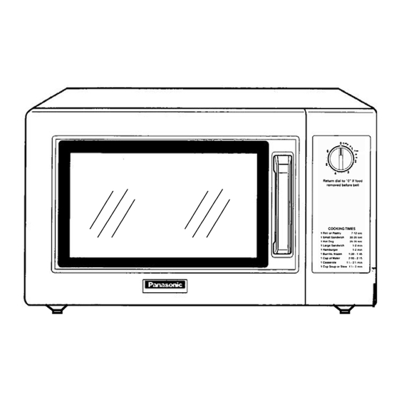
Summary of Contents for Panasonic NE-1022F
-
Page 1: Microwave Oven
ORDER NO.PAPMOSH1201014CE Microwave Oven NE-1022F APH (USA) © Panasonic Appliances Microwave Oven (Shanghai) Co., Ltd. 2012. - Page 2 NE-1022F...
-
Page 3: Table Of Contents
NE-1022F CONTENTS Page Page 1 CONTROL PANEL 5.5. Magnetron 2 SCHEMATIC DIAGRAM 5.6. Diode 3 CAUTIONS TO BE OBSERVED WHEN TROUBLESHOOTING 6 5.7. Protector diode 3.1. Check the grounding 6 MEASUREMENTS AND ADJUSTMENTS 3.2. Warning about the electric charge in the high voltage 6.1. -
Page 4: Control Panel
NE-1022F 1 CONTROL PANEL... -
Page 5: Schematic Diagram
NE-1022F 2 SCHEMATIC DIAGRAM... -
Page 6: Cautions To Be Observed When Troubleshooting
NE-1022F 3 CAUTIONS TO BE OBSERVED WHEN TROUBLESHOOTING Unlike many other appliances, the microwave oven is high 3.3. Part replacement. voltage, high current device. Though it is free from danger in When troubleshooting any part of component is to be replaced, ordinary use, extreme care should be taken during repair. -
Page 7: Disassembly And Parts Replacement Procedure
NE-1022F 4 DISASSEMBLY AND PARTS REPLACEMENT PROCEDURE 4.1. Magnetron 4.2. Fan motor 1. Discharge the high voltage capacitor. 1. Disconnect 2 lead wires from fan motor terminals. 2. Remove 2 screws holding magnetron thermal cutout. 2. Disconnect 2 lead wires from fuse holder terminals. -
Page 8: Door Assembly
NE-1022F 4.4. Door assembly NOTE: Always perform the microwave leakage measurement 1. Open the door and remove door C from door E by carefully test after installation and adjustment of door assembly. pulling outward starting from upper right hand corner. -
Page 9: Component Test Procedure
NE-1022F 5 COMPONENT TEST PROCEDURE WARNING 5.4. High voltage capacitor 1. High voltage is present at the high voltage terminal of the high voltage transformer during any cook cycle. 1. Check continuity of capacitor with meter on highest OHM 2. It is neither necessary nor advisable to attempt measurement of the scale. -
Page 10: Diode
NE-1022F 5.6. Diode 1. Isolate the diode from the circuit by disconnecting the leads. 2. With the ohmmeter set on the highest resistance scale, measure the resistance across the diode terminals. Reverse the meter leads and again observe the resistance reading. -
Page 11: Measurements And Adjustments
NE-1022F 6 MEASUREMENTS AND ADJUSTMENTS 6.1. Adjustment of primary interlock switch, secondary interlock switch and monitor interlock switch. 1. Mount the Primary interlock switch, the Secondary interlock switch and the Monitor Interlock switch to the door hook 6.2. Measurement of microwave assembly as shown in illustration. -
Page 12: Procedure For Measuring Microwave Energy Leakage
NE-1022F 7 PROCEDURE FOR MEASURING MICROWAVE ENERGY LEAKAGE 7.2.1. Measurement with the outer panel removed. Whenever you replace the magnetron, measure for radiation leakage before the outer panel is installed and after all necessary components are replaced or adjusted. Special care should be taken in measuring around the magnetron. -
Page 13: At Least Once A Year, Have The Radiation Monitor Checked
NE-1022F 7.4. At least once a year, have the radiation monitor checked for calibration by its manufacturer. -
Page 14: Troubleshooting Guide
NE-1022F 8 TROUBLESHOOTING GUIDE DANGER: HIGH VOLTAGES 1. Ensure proper grounding before troubleshooting. 2. Be careful of high voltage circuit. 3. Discharge high voltage capacitor. 4. When checking the continuity of the switches or the high voltage transformer,disconnect one lead wire from these parts and then check continuity with the AC plug removed. -
Page 15: How To Check The Semiconductors Using An Ohm Meter
NE-1022F 8.1. How to check the semiconductors using an OHM meter... -
Page 16: Exploded View And Parts List
NE-1022F 9 EXPLODED VIEW AND PARTS LIST 9.1. EXPLODED VIEW... -
Page 17: Parts List
NE-1022F 9.2. PARTS LIST NOTE: 1. When ordering replacement part(s), please use part number(s) shown in this part list. Do not use description of the part. 2. Important safety notice: Components identified by mark have special characteristics important for safety. -
Page 18: Escutcheon Base Assembly
NE-1022F 9.3. ESCUTCHEON BASE ASSEMBLY Ref. No. Part No. Part Name & Description Pcs/Set Remarks F00078K70AP NAME PLATE F60018K20AP TIMER SWITCH F80206P00AP TIMER KNOB F80346P00AP ESCUTCHEON BASE F80356P00AP ESCUT FACIA XTWEFNE3+8Q SCREW F800L8K20SAP ESCUTCHEON BASE (BU) -
Page 19: Door Assembly
NE-1022F 9.4. DOOR ASSEMBLY Ref. No. Part No. Part Name & Description Pcs/Set Remarks F02459660AP DHHS LABEL F30063700BP UPPER HINGE (A) F3018-1480 DOOR KEY A F30214000AP DOOR KEY SPRING XTN3+8BJ SCREW F30858960HN DOOR C F302K3700BP DOOR E (U) F31454J50XN DOOR SCREEN A... -
Page 20: Wiring Materials
NE-1022F 9.5. WIRING MATERIALS Ref. No. Part No. Part Name & Description Pcs/Set Remarks F030A8K20AP LEAD WIRE HARNESS F606V8K00CP PROTECTOR DIODE (U) -
Page 21: Packing And Accessories
NE-1022F 9.6. PACKING AND ACCESSORIES Ref. No. Part No. Part Name & Description Pcs/Set Remarks F00036P00AP OPERATING INSTRUCTION F01028K70SAP PACKING CASE, PAPER F01048K00AP UPPER FILLER F01058K00AP LOWER FILLER F01068K00AP P.E.BAG F01074W00AP DOOR SHEET F01924T00AP SHEET F01088K00AP TRAY PACKING F04243130AP SECURITY...


Need help?
Do you have a question about the NE-1022F and is the answer not in the manual?
Questions and answers