Table of Contents
Advertisement
Advertisement
Table of Contents

Summary of Contents for Liebert Prop Fan Condensing Unit
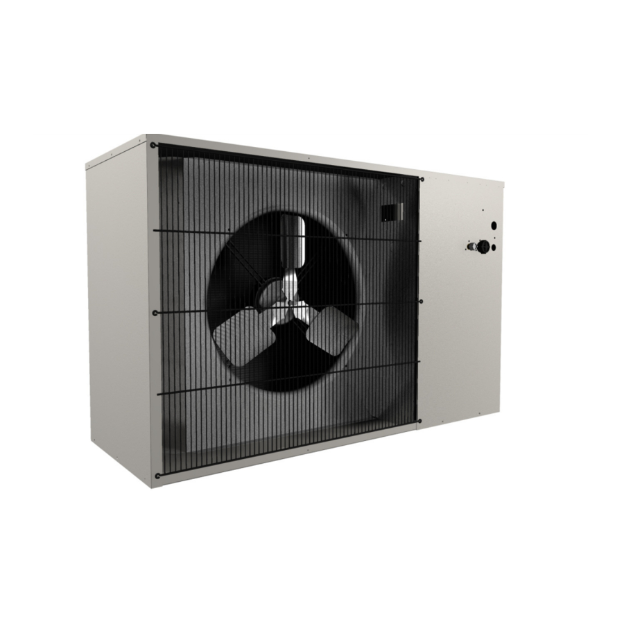
- Page 1 Liebert Prop Fan Condensing Unit ® ™ User Manual–50 & 60Hz...
- Page 2 Nominal Capacity — = Standard Coil L = 95°F (35°C) Ambient Unit with Hot-Gas 1000 BTU/Hr C = Coated Coil Liebert Lee-Temp Bypass H = 105°F (41°C) Ambient Liebert Lee-Temp 0 = Standard Noise Level A = Air Cooled P = 208/230-1ph-60Hz...
-
Page 3: Table Of Contents
1.1.3 Liebert Quiet-Line Models ........... . 1 Optional Equipment . - Page 4 Table 7 Refrigerant charge in Liebert pre-charged R-407C line sets ......16 ®...
-
Page 5: Product Description
Standard features include crankcase heater, high-pressure switch, condenser coil, sight glass, filter drier, hot gas bypass system with liquid quenching valve, direct drive propeller fan and motor, and Liebert Lee-Temp flood-back head pressure control. -
Page 6: Installation
Installation NSTALLATION Read this entire installation section before starting installation. This section details dimensional, electrical and piping information and specifications that affect the placement of the PFH unit in relation the connected evaporator unit, other outside units, barriers and walls. Be particularly mindful of service and airflow clearances and maximum equivalent piping distances and in elevation differences between PFH and connected evaporator unit. -
Page 7: Dimensional Data
Installation Dimensional Data Figure 1 Dimensions, horizontal air discharge Removable (right) panel Fan Rotation for access to refrigeration component (left side) Right Air Discharge Left Air Intake Shaded area indicates a minimum clearance of 18" (457mm) for proper air flow. Shaded area indicates a recommended clearance of 24"... -
Page 8: Figure 2 Dimensions, Top Air Discharge
Installation Figure 2 Dimensions, top air discharge Top Air Guard Height Discharge Fan Rotation Right Air Intake Shaded area Left Air indicates a minimum Intake clearance of 18" (457mm) for proper air flow. 2" (51mm) Shaded area indicates a minimum Removable panel for access Shaded area clearance of 18"... -
Page 9: Figure 3 Dimensional Data, 277V Step-Down Transformer
WALL MOUNTING RIGID MOUNTING Notes: 1. 1D18214P1 = Acme catalog no. T-1-37921 for all small systems except 3-ton Liebert DataMate with integral condenser. 2. 1D18214P2 = Acme catalog no. T-1-37922 for 3-ton Liebert DataMate with integral condenser. 3. Epoxy coated. Suitable for indoor/outdoor service. Horizontal- or vertical-mount. -
Page 10: Piping And Electrical Connections
Installation Piping and Electrical Connections Figure 4 Piping and electrical connections, horizontal discharge Liquid Line Suction Line Quick Connect Quick Connect (Male Coupling) (Male Coupling) Electrical Entrance for High-Voltage Connection Electrical Entrance for Low-Voltage Connection DPN000132 Rev. 1 Table 3 Electrical and piping connections, horizontal air discharge Model Numbers Electrical Connections, in (mm) -
Page 11: Figure 5 Piping And Electrical Connections, Top Air Discharge
Installation Figure 5 Piping and electrical connections, top air discharge * System 2 (5 Ton) Electrical Entrance for High-Voltage Connection Liquid Line Quick Connect Electrical Entrance for (Male Coupling) Low-Voltage Connection * System 1 (3 Ton) Suction Line Quick Connect DPN000133 (Male Coupling) Rev. -
Page 12: Figure 6 General Piping Arrangement
Male Quick Sight Connect Coupling Hot Gas Bypass Check Valve Glass Control Valve Liquid Injection Valve Liquid Line Solenoid Valve Liebert Lee-Temp Receiver Heater Receiver Pressure Limiting Pressure Balancing Switch Valve Liquid Line Male Quick Connect Coupling SINGLE CIRCUIT SHOWN DPN000129 * Scroll compressor, except 1Ton, 60Hz is reciprocating compressor. -
Page 13: Figure 7 Electrical Field Connections, 1- To 5-Ton Units
(5 Ton High Ambient or 5 Ton Quiet-Line) Electric service connection Factory-wired to contactor or terminal block to components on electric panel Single- or three-phase electric service not provided by Liebert High-voltage electric power supply entrance Heat rejection connection. Low-voltage electric Field-supplied 24V NEC power supply Class 2 wiring. -
Page 14: Figure 8 Electrical Field Connections, 8-Ton Units
Electric service Factory-wired connection to contactor to components on or terminal block electric panel Single- or three-phase electric service not provided by Liebert High-voltage Heat rejection connection. electric power Field-supplied 24V NEC supply entrance Class 2 wiring. Low-voltage electric... -
Page 15: Figure 9 Single-Phase, 1-3 Ton Model Schematic, Typical
Installation Figure 9 Single-phase, 1-3 ton model schematic, typical Conductors Field-Supplied (See Note 5) NOMENCLATURE OUTDOOR CONDENSING MODULE EVAPORATOR UNIT Standard Devices BDR -- Bleed Resistor Unit Alarm Input C1 -- Condenser Contactor Connection CAP1 -- Compressor Capacitor CAP2 -- Fan Motor Capacitor CAP3 -- Compressor Capacitor 24V Power Supply... -
Page 16: Figure 10 Three-Phase, 3-5 Ton Model Schematic, Typical
Installation Figure 10 Three-phase, 3-5 ton model schematic, typical Conductors Field-Supplied (See Note 5) NOMENCLATURE OUTDOOR CONDENSING MODULE EVAPORATOR UNIT Standard Devices Unit Alarm C1 -- Condenser Contactor Input CAP2 -- Fan Motor Capacitor Connection CHTR -- Compressor Heater COMP -- Compressor F1 -- Transformer Fuse 1 24V Power F2 -- Transformer Fuse 2... -
Page 17: Figure 11 Three-Phase, 8 Ton Model Schematic, Typical
Installation Figure 11 Three-phase, 8 ton model schematic, typical Conductors Field-Supplied (See Note 5) OUTDOOR CONDENSING MODULE STANDARD DEVICES Evaporator Unit C1 - Compressor Contactor 1 HIGH HEAD 1 C2 - Compressor Contactor 2 See Note 6 CHTR1 - Compressor Heater 1 COOLING 1 CHTR2 - Compressor Heater 2 C1 Aux. -
Page 18: Piping Considerations
The 8-ton Liebert Mini-Mate2 split system units will require four refrigerant lines between the evaporator and condensing units. Each refrigeration circuit will need one insulated copper suction line and one copper liquid line. -
Page 19: Figure 12 Refrigerant Piping Diagram
Installation Figure 12 Refrigerant piping diagram Pitch down 1/2" (13mm) per 10 ft. (3m) Evaporator NOTE When installing remote condensing units below the NOTE evaporator, the suction gas line should be trapped When installing remote condensing units below the with an inverted trap to the height of the evaporator. evaporator, the suction gas line should be trapped with This prevents refrigerant migration to the compres- an inverted trap to the height of the evaporator . -
Page 20: Pre-Charged Line Sets
Use a soft, flexible material to pack around the tubes when sealing openings in walls to prevent tube damage and to reduce vibration transmission. Table 7 Refrigerant charge in Liebert pre-charged R-407C line sets Line Size, Length, Charge R-407C, ft. -
Page 21: Table 8 Liebert ® Pfh Unit Charge Levels And Coupling Size
Installation ® Table 8 Liebert PFH unit charge levels and coupling size Model Numbers R-407C Charge Coupling Size 60 Hz 50 Hz lb-oz (kg) Liquid Suction 95°F (35°C) Standard Sound PFH014A-_L7 — PFH020A-_L7 — 8-6 (3.80) PFH027A-_L7 — PFH037A-_L7 PFH036A-_L7 13-5 (6.04) -
Page 22: Installation Of Piping To Units
2.5.5 R-407C PFH Installed as a Replacement Condensing Unit in an R-22 System When replacing the condensing unit of an existing Liebert split system containing R-22 and mineral oil, the following should be considered. 1. Check for proper operation of the system prior to replacing the outdoor unit. If this is not possible, at minimum perform a leak check to ensure that the components that remain (line set, evaporator) are leak tight. - Page 23 Installation Remove Existing Condensing Unit 1. Recover refrigerant in system using proper refrigeration practices. 2. Oil removal: The majority of the oil will be in the old condensing unit (compressor, condenser and receiver), which will be replaced with the new unit. 3.
-
Page 24: General System Charge Requirements
Evaporator Charge R-407C Models oz (kg) Indoor Unit MMD12E 3 (0.085) MMD18E 4 (0.113) MMD24E 7 (0.198) ™ Liebert Mini-Mate2 MMD35/36E 7 (0.198) MMD59/60E 4 (0.113) MMD95/96E 7 (0.198) each circuit DME020E 4 (0.113) ™ Liebert DataMate DME027E 5 (0.141) DME037E 6.5 (0.184) -
Page 25: Electrical Connections
Installation Electrical Connections Each unit is shipped from the factory with all internal wiring completed. All power, control wiring and ground connections must be made in accordance with the National Electrical Code and local codes. Refer to equipment nameplate regarding wire size and circuit protection requirements. Refer to Figures 5, 7 and 8 and electrical schematic (reference Figures 9 through 11) when making connections. -
Page 26: Low-Voltage Control Wire Sizing
Installation 2.6.2 Low-Voltage Control Wire Sizing Low-voltage wiring should be sized to allow a 1 volt maximum drop due to line resistance between the evaporator and condensing unit. Use NEC Class 1 or 2 wiring according to wire routing conditions chosen, local codes and application limits in Tables 14 and 15. -
Page 27: Table 17 Electrical Data-High Ambient Models (105°F/41°C) 60Hz
Installation Table 17 Electrical data—High ambient models (105°F/41°C) 60Hz Nominal Input Voltage-Phase Capacity, * Electrical Model # Tons Characteristic 208/230-1 208/230-3 460-3 575-3 15.4 — — — 18.4 — — — — — — 20.5 15.4 24.8 18.4 — 17.0 —... -
Page 28: Checklist For Completed Installation
Installation Table 20 Electrical data—High ambient models (105°F/41°C) 50Hz Nominal Input Voltage-Phase Capacity * Electrical Model # Tons Characteristic 220-1 380/415-3 20.5 — — 11.7 — — FLA = Full Load Amps Table 21 Electrical data—Quiet-Line models (95°F/35°C) 50Hz Nominal Input Voltage-Phase Capacity * Electrical... -
Page 29: Operation
• Dirty condensing coils • Crimped lines ® ™ Liebert Lee-Temp Flood Back Head Pressure Control Outdoor condensing unit components for head pressure control include a receiver, heater and three-way head pressure control valve. The head pressure control valve operates to maintain a minimum condensing pressure. -
Page 30: Hot Gas Bypass
Operation Hot Gas Bypass 3.4.1 Operation When applying hot gas bypass with split system condensing units, bypassing discharge gas to the compressor suction line offers more flexibility than conventional hot gas bypass to the evaporator unit. The hot gas bypass valve is installed between the compressor discharge piping and suction piping, bypassing the condenser and evaporator coils. -
Page 31: Maintenance
Maintenance AINTENANCE General Access the condensing unit by removing the unit housing panel. Clean the air cooled condenser coil of all debris that will inhibit airflow. This can be done with compressed air or with a commercial coil cleaner. Check for bent or damaged coil fins and repair as necessary. During winter, do not permit snow to accumulate on or around the condensing unit. -
Page 32: Electrical Failure-Burnout
Maintenance 4.2.1 Electrical Failure—Burnout In the event that there is an electrical failure and a complete burnout of the refrigeration compressor motor, the proper procedures must be performed in order to clean the system to remove any acids that would cause a future failure. NOTE Failure to properly clean the system after a compressor motor burnout will void the compressor warranty. -
Page 33: Field Charge Verification
Maintenance Field Charge Verification An integral sight glass is provided with the receiver to assist in field charge verification. During charge verification set the control temperature down to keep the system running. If the system is equipped with hot gas bypass, de-energize it by removing power from the hot gas solenoid valve coil. To remove power, disconnect the solenoid leads from the unit contactor in the electric box (refer to specific unit schematic;... -
Page 34: Troubleshooting
Troubleshooting ROUBLESHOOTING Table 23 Troubleshooting Problem Cause Remedy No power to unit Check voltage at input terminal block. Check for 24VAC ±2VAC at control connections 1 & 2. If no voltage, check control setting requires cooling. If there Compressor contactor not pulling in is voltage, lockout relay may be energized. - Page 36 +39 049 9719 111 Fax: +39 049 5841 257 While every precaution has been taken to ensure the accuracy and completeness of this literature, Liebert Corporation assumes no Asia responsibility and disclaims all liability for damages resulting from use of 29/F, The Orient Square Building this information or for any errors or omissions.
Need help?
Do you have a question about the Prop Fan Condensing Unit and is the answer not in the manual?
Questions and answers