Advertisement
Advertisement

Related Manuals for Pro-Built Tools PB1200 Series

Summary of Contents for Pro-Built Tools PB1200 Series
- Page 1 Pro-Built Tools PB1200 User’s Guide 70’ 16” 100’ 20” 120’ 512hz Built in Sonde...
- Page 2 Pro-Built Tools...
-
Page 3: Table Of Contents
TABLE OF CONTENTS Diagram & Equipment Specifications..4 Safety Instructions........5 Pro-Built............6 Pro-Built with Diagram........7 Tips in the Field........8-9 Trouble Shooting.........10-16 Warranty Information........17... -
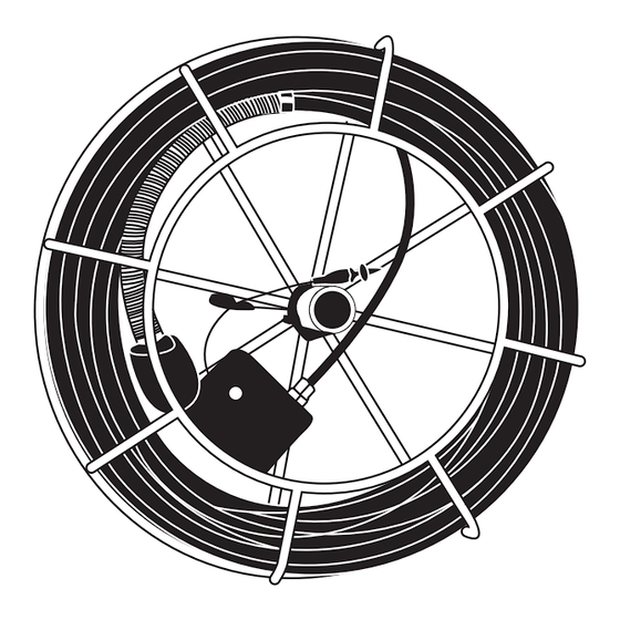
Page 4: Diagram & Equipment Specifications
DIAGRAM & SPECIFICATIONS A .Inductive Locator Terminal B. Camera Head C. Video In/Out D. Heat Treated Epoxy Sealed SV Cable... -
Page 5: Safety Instructions
EQUIPMENT SPECIFICATIONS • PB1200 Camera Head Dimension: 1 1/4” Diameter Pipe Size: 2“ Pipe + (2” Pipe Depends on Condition of Pipe) • High Tension Pro Built Inspection Cable Push Capacity: 100’ – 500’ (depending on condition of line) • Steel Cage 16”... -
Page 6: Pro-Built
Pro-Built Tools PB1200 Series Inspection Camera Once you have inspected all components to make sure that they are not damaged or broken, plug the power cord into a grounded outlet. The camera should turn on. Check to see if the lights on your camera head are on. -
Page 7: Pro-Built With Diagram
Pro-Built Tools At this point you will plug the free end of your video cable into the monitor that you are using to view the camera with. Please refer to monitor manual for any further instruction. If your camera model came equipped with a 512 Hz transmitter built inside the camera head please see the diagram below to activate the built in transmitter. -
Page 8: Tips In The Field
TIPS IN THE FIELD 1.) Run water down line to keep sapphire window clean and clear. Jiggle the head a little bit in the water for best clarity. 2.) If you stand too far back while pushing cable it may cause the cable to kink. - Page 9 TIPS IN THE FIELD cont. 5.) DO NOT hammer or slam the camera into pipe where it is just not pushing through. Use the technique described on tip 4. After you are comfortable with your system it may be easier to push thru the pipe fast and slowly pull back for your actual inspection.
-
Page 10: Trouble Shooting
TROUBLE SHOOTING The trouble shooting guide lines below are designed to help you out in the field. If you cannot figure out the problem or fix it without voiding your warranty, please call the number listed in the back of your manual to speak with a repair technician. - Page 11 TROUBLE SHOOTING VIDEO WORKS–LIGHTS DON’T TURN ON Possible Problems: -Lights Burnt out -Dimmer Control Switch Turned Down -Dimmer Control Switch Broken -Broken or loose connection in Camera Head. TRY THIS: Turn dimmer control all the way down and then all the way back up.
- Page 12 TROUBLE SHOOTING TRY THIS: First check to see if your GFCI is tripping. Try to plug the unit into another location with different electricity. If GFCI will not re-set it is not working and will prevent the camera system from turning on. IF GFCI IS REMOVED FROM UNIT AND THEN CAMERA SYSTEM IS USED WITH OUT IT, WARRANTY WILL BE VOID.
- Page 13 TROUBLE SHOOTING TRY THIS: If the transmitter that is built inside the camera head is in the ON position, the frequency that it puts out interferers with the camera head frequency, and will create wavy lines across your monitor. Inspect your pipe and then locate to avoid picture distortion.
- Page 14 TROUBLE SHOOTING “NO SIGNAL” FLASHING ON MONITOR Possible Problems: -Wrong setting set on Monitor or Recording Device -Faulty Video Cable -Broken or damaged monitor or recording device -Broken or loose connection in camera head or control box. TRY THIS: Read Monitor or Recording Device instruction manual to make sure you are on the proper settings.
- Page 15 TROUBLE SHOOTING BLURRY OR SCRAMBLED PICTURE Possible Problems: -Monitor Broken or Damaged -Seal broken or compromised -Moisture in head -Camera Head Fried -Faulty Video Cable TRY THIS: First plug the camera system into another monitor or standard television that accepts standard RCA connections.
- Page 16 TROUBLE SHOOTING COLORFUL IMAGES DISTORTED COLORS Possible Problems: -Monitor Broken or Damaged -Seal broken or compromised -Moisture in head -Camera Head Fried -Faulty Video Cable TRY THIS First plug the camera system into another monitor or standard television that accepts standard RCA connections.
-
Page 17: Warranty Information
WARRANTY INFORMATION For warranty or service work please contact manufacture ProBuilt Tools. Read following information for contact details. Pro-Built Tools service center 11711 Coley River Circle, Ste #11 Fountain Valley, CA 92708 Phone: (714) 437-1255...
Need help?
Do you have a question about the PB1200 Series and is the answer not in the manual?
Questions and answers