Advertisement
Table of Contents
- 1 Table of Contents
- 2 Diagram & Equipment Specifications
- 3 Equipment Specs & Safety Instructions
- 4 Control Panel
- 5 Initial Setup Guide
- 6 Locating
- 7 Digital On-Screen Footage Counter
- 8 SD Recorder
- 9 Tips in the Field
- 10 No Video/Signal" Guide
- 11 Trouble Shooting
- 12 Head Removal & Installation
- 13 Warranty & Contact Information
- Download this manual
Advertisement
Table of Contents

Related Manuals for Pro-Built Tools PB-Mycro

Summary of Contents for Pro-Built Tools PB-Mycro
- Page 1 Pro-Built Tools User’s Guide 100’ 275’ PB Mycro 130’ 300’ PB2000 PB2400ES 150’ 400’ PB3600ES 200’ 500’ 250’...
-
Page 3: Table Of Contents
TABLE OF CONTENTS Diagram & Equipment Specifications...4 Equipment Specs & Safety Instructions..5 Control Panel..........6 Initial Setup Guide........7 Locating.............8-9 Digital On-Screen Footage Counter...10 SD Recorder..........11-13 Tips in the Field........14-15 “No Video/Signal” Guide.......16-17 Trouble Shooting........18-20 Head Removal & Installation......21-23 Warranty & Contact Information......24 www.probuilttools.com... -
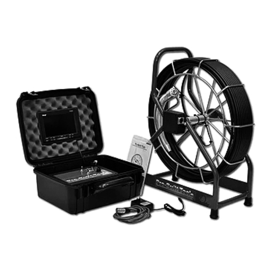
Page 4: Diagram & Equipment Specifications
DIAGRAM & SPECIFICATIONS A. Camera Head Included Not Pictured B. Patch Cord Input (Reel Side) - Control Box - See Page 7 Diagram C. Cable Guide - CAT-6 Patch Cord. D. Powder Coated Frame E. Heat Treated Epoxy Sealed SV Cable F. -
Page 5: Equipment Specs & Safety Instructions
EQUIPMENT SPECIFICATIONS • Pro-Built Standard Fixed Head Dimension: 1.29” Diameter Pipe Size: 2“ Pipe + (2” Pipe Depends on Condition of Pipe) • Pro-Built Self Leveling Head Dimension: 1.95” Diameter Pipe Size: 3“ Pipe + (3” Pipe Depends on Condition of Pipe) •... -
Page 6: Control Panel
CONTROL PANEL Main Controls: Power – On/Off Switch Dimmer Control – Dim LED Lights as Needed Connection to Reel – Input Cat 6 Patch Cord Video Output – Input any monitoring device Sonde – Turn on to activate 512 Hz Sonde Power Cord –... -
Page 7: Initial Setup Guide
INITIAL SETUP GUIDE Models: PB2000, PB-Mycro, PB2400ES, PB3600ES Upon initial receipt of your equipment, first check that your shipment has arrived intact. Please note any physical damages to the shipping box and/or equipment. Any such damages should be reported immediately so that a shipping claim can be made. -
Page 8: Locating
LOCATING YOUR CAMERA Models: PB2000, PB-Mycro, PB2400ES, PB3600ES After you’ve pushed your camera through the pipe and have decided that you are at a point where you would like to determine the location and depth of your camera head, please follow these steps: 1) Turn on your “Sonde”... - Page 9 LOCATING YOUR CAMERA Models: PB2000, PB-Mycro, PB2400ES, PB3600ES 2) After your sonde is activated, it is time to use your locator. This page specifically shows how to use your PB550SL Digital Locator Wand in conjunction with your PB Series sewer camera.
-
Page 10: Digital On-Screen Footage Counter
DIGITAL ON-SCREEN FOOTAGE COUNTER Models: PB2000, PB-Mycro, PB2400ES, PB3600ES Your installed Digital On-Screen Footage Counter will display on the screen as follows: The control panel for the Digital On-Screen Footage Counter is on the left half of your main controller: The controls are as follows: 1) Reset –... -
Page 11: Sd Recorder
SD RECORDER SETUP & USE GUIDE Models: PB2000, PB-Mycro, PB2400ES, PB3600ES If you purchased your SD Card Recorder as an option along with your camera system, it will already be installed into your Control Box. Please refer to the end of this guide for installation instructions if purchased separately. - Page 12 The SD Card Recorder has options to record on power-up or by manually beginning and ending the recording. You may adjust those in the menu as shown: “Manual” is the preferred method for setting up a recording. After applying the setting (which will be saved in the device memory), simply point your remote at the recorder and press “OK”...
- Page 13 INSTALLING THE SD RECORDER TO YOUR SYSTEM 1) Route an RCA Cable from your SILVER “Video Out” jack on the top of the control box to the WHITE “Video IN” plug on the back of the recorder. 2) Route the WHITE “Video OUT” plug from the back of the recorder to the YELLOW RCA jack behind your Controller.
-
Page 14: Tips In The Field
TIPS IN THE FIELD 1.) Run water down line to keep sapphire window clean and clear. Jiggle the head a little bit in the water for best clarity. 2.) If you stand too far back while pushing cable it may cause the cable to kink. - Page 15 Pulling the camera back is always easier than pushing it through 6.) Pro-Built Tools Camera Systems have an automatic light adjustment. If the automatic light adjustment is not enough due to unusual circumstances in different or difficult pipe use your dimmer control knob to adjust for better picture quality.
- Page 16 GUIDE TO “NO VIDEO/SIGNAL” Models: PB2000, PB-Mycro, PB2400ES, PB3600ES “BLUE SCREEN” 1) Check that your camera head LEDs are powered on. a) If they are not, and your LCD is “Blue Screen”, check that your pin connector is still plugged into the back of your camera head.
- Page 17 GUIDE TO “NO VIDEO/SIGNAL” Models: PB2000, PB-Mycro, PB2400ES, PB3600ES “BLACK SCREEN” 1) Check that your camera head LEDs are powered on. a) If they are not, and your LCD is “Black Screen”: Make sure that your power supply is plugged into a wall receptacle that has confirmed good power.
-
Page 18: No Video/Signal" Guide
TROUBLE SHOOTING VIDEO WORKS–LIGHTS DON’T TURN ON Possible Problems: -Lights Burnt out -Dimmer Control Switch Turned Down -Dimmer Control Switch Broken -Broken or loose connection in or to Camera Head. TRY THIS: 1) Turn dimmer control all the way down and then all the way back up. - Page 19 TROUBLE SHOOTING HORIZONTAL WAVY LINES ACROSS SCREEN Possible Problems: -512 Hz Sonde Switch is in the ON position - Turn Switch to the OFF position -Faulty Video Cable or Connector - Clean or replace video connectors/cables -Dirty Monitor - Clean LCD (powered down) with damp cloth If problem persists, please contact a technician at the number in the back of this manual.
- Page 20 TROUBLE SHOOTING BLURRY / SCRAMBLED / DISTORTED PICTURE Possible Problems: -Monitor Broken or Damaged - See “No Video/Signal” Guide -Faulty Video Cable / Connection - See “No Video/Signal” Guide -Moisture in Camera Head - Visually inspect camera head for signs of moisture inside of lens.
-
Page 21: Head Removal & Installation
3) Using your hands, rotate the spring in the SAME DIRECTION as the rungs (facing the camera head) and PULL the head from the spring - This motion DECOMPRESSES the spring from head. NOTE: Pro-Built Tools recommends that you send your equipment to an authorized service center and have an authorized Pro-Built Tools Technician work on your product. - Page 22 Once unthreaded, it will pull back from the camera head VERY EASILY. NOTE: Pro-Built Tools recommends that you send your equipment to an authorized service center and have an authorized Pro-Built Tools Technician work on your product.
- Page 23 10) Remove any zip ties applied to the reel for stabilization and return the camera head assembly to the reel. NOTE: Pro-Built Tools recommends that you send your equipment to an authorized service center and have an authorized Pro-Built Tools Technician work on your product.
-
Page 24: Warranty & Contact Information
At no time is ProBuilt Tools, Inc. responsible for loss of work while equipment is in for service. For Warranty Work please contact our service center. CONTACT INFORMATION Pro-Built Tools 214-503-0402 www.probuilttools.com...
Need help?
Do you have a question about the PB-Mycro and is the answer not in the manual?
Questions and answers