Table of Contents
Advertisement
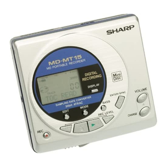
Illustration: MD-MT15/15C
Illustration: MD-MT15H/15W
Illustration: MD-MT161E/18H (Only printing is different.)
The machine MD-MT15/MT15C/MT15W is a modification of
MD-MT20/MT20C/MT20W the difference is the Top Cabinet.
Its performance and operation are identical with those of MD-
MT20/MT20C/MT20W. For details refer to the service manual
(No.S6943MDMT20//) for MD-MT20/MT20C/MT20W.
MD-MT20/MT20C/MT20W
REMOVING AND REINSTALLING THE MAIN PARTS 11
ADJUSTMENT .............................................................. 12
TROUBLE SHOOTING ................................................. 37
FUNCTION TABLE OF IC ............................................ 40
CIRCUIT DESCRIPTION .............................................. 42
CONTENTS OF MD-MT15/15C/15H/15W/161E/18H
SAFETY PRECAUTION FOR SERVICE MANUAL (MD-MT15W/15H/18H/161E ONLY) ..................................................... 2
SPECIFICATIONS ................................................................................................................................................................. 3
NAMES OF PARTS ............................................................................................................................................................... 4
OPERATION MANUAL .......................................................................................................................................................... 5
QUICK GUIDE (MD-MT15 ONLY) ......................................................................................................................................... 8
DISASSEMBLY .................................................................................................................................................................... 10
NOTES ON SCHEMATIC DIAGRAM .................................................................................................................................. 11
TYPES OF TRANSISTOR AND DIODE .............................................................................................................................. 11
VOLTAGE ............................................................................................................................................................................ 12
BLOCK DIAGRAM ............................................................................................................................................................... 13
SCHEMATIC DIAGRAM ...................................................................................................................................................... 14
WIRING SIDE OF P.W.BOARD ........................................................................................................................................... 17
WAVEFORMS OF MD CIRCUIT ......................................................................................................................................... 22
PARTS GUIDE/EXPLODED VIEW
SERVICE MANUAL
Page
- 1 -
MD-MT15/15C/15H/15W/161E/18H
MD-MT15(S)
MD-MT15C(S)
MD-MT15H(RD)
MD-MT15H(S)
MD-MT15W(S)
MD-MT161E(S)
MD-MT18H(GR)
• In the interests of user-safety the set should be restored to its
original condition and only parts identical to those specified be
used.
The machine MD-MT15H/MT161E/MT18H is a modification
of MD-MT20H/MT16E the difference is the Top Cabinet. Its
performance and operation are identical with those of MD-
MT20H/MT16E. For details refer to the service manual (No.
S5933MDMT20H/) for MD-MT20H/MT16E.
MD-MT20H/MT16E
REMOVING AND REINSTALLING THE MAIN PARTS .. 9
ADJUSTMENT .............................................................. 10
TROUBLE SHOOTING ................................................. 35
FUNCTION TABLE OF IC ............................................ 38
CIRCUIT DESCRIPTION .............................................. 40
This document has been published to be used
for after sales service only.
The contents are subject to change without notice.
No. S7946MDMT15//
Page
Page
Advertisement
Table of Contents

Related Manuals for Sharp MD-MT15S


Summary of Contents for Sharp MD-MT15S
-
Page 1: Table Of Contents
PARTS GUIDE/EXPLODED VIEW PACKING OF THE SET (MD-MT15 FOR U.S.A. ONLY) PACKING METHOD (MD-MT161E ONLY) This document has been published to be used SHARP CORPORATION for after sales service only. The contents are subject to change without notice. – 1 –... -
Page 2: Adjustment
MD-MT15/15C/15H/15W/161E/18H SAFETY PRECAUTION FOR SERVICE MANUAL (MD-MT15W/15H/18H/161E ONLY) Precaution to be taken when replacing and servicing the Laser Pickup. The AEL (Accessible Emission Level) of Laser Power Output for this model is specified to be lower than Class I Requirements. However, the following precautions must be observed during servicing to protect your eyes against exposure to the laser beam. -
Page 3: Specifications
MD-MT15/15C/15H/15W/161E/18H FOR A COMPLETE DESCRIPTION OF THE OPERATION OF THIS UNIT, PLEASE REFER TO THE OPERATION MANUAL. SPECIFICATIONS MD-MT15H MD-MT15/15C Power source: DC 3.0V: Commercially available, “AA” (LR6) size, alkaline General battery x 2 DC 5V: AC adaptor (AC 120V, 60 Hz) Power source: DC 2.4V: Optional Rechargeable Nickel-Metal Hydride bat-... -
Page 4: Names Of Parts
MD-MT15/15C/15H/15W/161E/18H NAMES OF PARTS 1. Monaural Long-Play Mode Indicator Illustration: MD-MT15/15C 2. Record Indicator 1 2 3 4 5 6 3. Level Meter 4. Fast Play Indicator 5. Repeat Indicator 6. TOC Indicator 7. Battery Indicator 8. Random Indicator 9. Track Number Indicator 10. -
Page 5: Operation Manual
MD-MT15/15C/15H/15W/161E/18H OPERATION MANUAL – 5 –... - Page 6 MD-MT15/15C/15H/15W/161E/18H – 6 –...
- Page 7 MD-MT15/15C/15H/15W/161E/18H – 7 –...
-
Page 8: Quick Guide (Md-Mt15 Only)
MD-MT15/15C/15H/15W/161E/18H QUICK GUIDE (MD-MT15 ONLY) – 8 –... - Page 9 MD-MT15/15C/15H/15W/161E/18H – 9 –...
-
Page 10: Disassembly
MD-MT15/15C/15H/15W/161E/18H DISASSEMBLY (B1)x2 Cares before disassembling Key Switch ø1.4x2mm When assembling the machine after disassembling or Top Cabinet repair, observe the following requirements so as to ensure (A1)x2 safety and performance. ø1.4x2mm (A1)x1 1. Remove the batteries from the machine, and take out the ø1.4x2mm mini-disc. -
Page 11: Notes On Schematic Diagram
MD-MT15/15C/15H/15W/161E/18H NOTES ON SCHEMATIC DIAGRAM • Resistor: • The indicated voltage in each section is the one measured To differentiate the units of resistors, such symbol as K and by Digital Multimeter between such a section and the chas- M are used: the symbol K means 1000 ohm and the symbol sis with no signal given. -
Page 12: Voltage
MD-MT15/15C/15H/15W/161E/18H VOLTAGE IC101 IC201 IC401 IC501 IC701 IC801 VOLTAGE PIN VOLTAGE PIN VOLTAGE VOLTAGE VOLTAGE VOLTAGE VOLTAGE VOLTAGE 0.88V 0.72V 2.5V 0.72V 0.2V 2.5V 2.5V 2.32V 2.5V 2.34V 0.72V 1.27V 0.72V 2.35V 0.73V 1.24V 1.25V 2.32V 1.24V 1.25V 0.18V 0.73V 0.71V 1.25V 2.34V... -
Page 13: Block Diagram
MD-MT15/15C/15H/15W/161E/18H J702 MIC IN J801 (READY FOR J703 Ni - MH Battery PLUG/IN DC IN JACK J701 J701 HEADPHONES POWER) (4~5.5V) OPTICAL IN LINE IN LINE Dry Battery (2 pieces) 1.7~3.4V IC901 SPINDLE MOTOR DRIVER BA6966FV 1, 3, 4, 5, 6,19,20 M903 M901... -
Page 14: Schematic Diagram
MD-MT15/15C/15H/15W/161E/18H P15 P16 MAIN PWB-A1 C112 0.033 L203 100mA C209 C111 C110 22P(CH) TP139 C107 C109 IC101 0.0033 0.22 C211 0.012 5P(CH) C106 RF SIGNAL PLAYBACK SIGNAL 0.22 PROCESSOR 47 46 45 44 43 42 41 39 38 37 RECORD SIGNAL R106 IR3R55 ROUT... - Page 15 MD-MT15/15C/15H/15W/161E/18H DADATA TP451 EDIT ADDATA TP452 DISP L203 DFCK TP453 SKIP 100mA BCLK C209 TP454 SKIP 22P(CH) LRCK HREC TP455 C211 TP456 P-MO 5P(CH) ADPON HSTOP TP457 STOP DAPON TP458 OPTCNT R455 R456 R457 TP459 HPLAY PLAY 5.6K 8.2K TP460 HKEY2 R458 BASS...
- Page 16 MD-MT15/15C/15H/15W/161E/18H • NOTES ON SCHEMATIC DIAGRAM can be found on page 11. • The numbers are waveform numbers shown in page 22. TP451 EDIT TP452 DISPLY LCD ASS'Y TP453 SKIP DOWN TP454 SKIP UP TP455 KEY SWITCH TP456 P-MODE FLEXIBLE TP457 STOP TP458...
-
Page 17: Wiring Side Of P.w.board
MD-MT15/15C/15H/15W/161E/18H MAGNETIC HEAD FLEXIBLE PWB(18) M901 SPINDLE MOTOR OPTICAL PICKUP UNIT(13) MAGNETIC HEAD(24) SW902 DISC MECHANISM PROTECT FLEXIBLE PWB PH901 CN601 PHOTO TO MAIN PWB INTERRUPTER P18 5-H M902 SLED MOTOR CN101 M903 HEAD TO MAIN PWB UP/DOWN MOTOR P18 4-H TO MAIN PWB P18 2-C TO MAIN PWB... - Page 18 MD-MT15/15C/15H/15W/161E/18H MAIN PWB-A1 (BOTTOM VIEW) R804 R269 TO AUDIO PWB Terminal, Battery IC805 CN702 (235) P20 3-A C258 R255 FLAT CABLE (243) R254 R262 C253 R261 To Key Switch Flexible Ass'y To LCD Ass'y P17 2-E P17 5-E Terminal, Battery (237) Terminal, Battery R252...
- Page 19 MD-MT15/15C/15H/15W/161E/18H MAIN PWB-A1 (TOP VIEW) R256 SW801 SW801 Ni-MH BATTERY DETECTION R250 IC806 R251 D812 IC803 F871 C805 R268 T0.5A L 63V C876 L821 L822 C600 R600 C874 L600 C821 C651 IC841 C609 L609 C605 C834 R833 C610 C875 C826 C863 IC702 C877...
- Page 20 MD-MT15/15C/15H/15W/161E/18H TO MAIN PWB AUDIO PWB-A2 (TOP VIEW) CN701 P18 2-B FLAT CABLE (243) CN702 L751 L752 L453 R764 R763 R765 R761 L454 C755 R769 R770 R753 R762 IC703 C491 C758 C756 R716 R754 C712 L703 R714 C757 C759 L704 C760 R757 L719...
- Page 21 MD-MT15/15C/15H/15W/161E/18H AUDIO PWB-A2 (BOTTOM VIEW) TP066 TP077 TP068 TP062 TP728 TP076 TP064 TP061 TP069 TP086 TP065 TP080 L452 TP093 TP727 TP063 TP082 TP067 TP072 TP092 TP724 TP729 TP070 TP089 J703 HEADPHONES TP722 TP721 TP723 TP071 TP070B TP721B TP725 TP064B TP074 TP726 L451 TP085...
-
Page 22: Waveforms Of Md Circuit
MD-MT15/15C/15H/15W/161E/18H WAVEFORMS OF MD CIRCUIT Stopped 1994 / 12 / 15 22:54:19 Stopped 1994 / 12 / 16 00:24:17 Stopped 1994 / 12 / 16 01:03:40 CH1=1mV CH2=500mV CH3=5V CH4=2V 50ms/div CH1=2V CH2=2V CH3=2V CH4=2V 50us/div CH1=1V CH2=2V CH3=500mV 2ms/div DC 10:1 DC 10:1 DC 10:1... - Page 23 “HOW TO ORDER REPLACEMENT PARTS” To have your order filled promptly and correctly, please furnish the For U.S.A. only following information. Contact your nearest SHARP Parts Distributor to order. 1. MODEL NUMBER 2. REF. No. 3. PART NO. 4. DESCRIPTION For location of SHARP Parts Distributor, Please call Toll-Free;...
- Page 24 MD-MT15/15C/15H/15W/161E/18H PRICE PRICE PARTS CODE DESCRIPTION PARTS CODE DESCRIPTION RANK RANK INTEGRATED CIRCUITS L500 RCILC0344AFZZ AC 47 H,Choke L600 RCILC0331AFZZ AC 2.2 H,Choke L601~604 RCILC0358AFZZ AC 4.7 H,Choke IC101 VHIIR3R55//-1 AQ RF Signal,Processor,IR3R55 L608~610 RCILC0358AFZZ AC 4.7 H,Choke IC200 VHI62FP2002-1 AE 2.0V Regulator,62FP2002 L702~704 RCILC0353AFZZ...
- Page 25 MD-MT15/15C/15H/15W/161E/18H PRICE PRICE PARTS CODE DESCRIPTION PARTS CODE DESCRIPTION RANK RANK C622 VCKYCY1CB104K AB 0.1 F,16V R254 VRS-CY1JB222J AA 2.2 kohms,1/16W C651 VCKYTV1CF105Z AB 1 F,16V R255 VRS-CY1JB225J AA 0.2 Mohms,1/16W R256 VRS-CY1JB183J AA 18 kohms,1/16W C701,702 VCSATA0JJ106M AD 10 F,6.3V,Electrolytic,Tantalum R257 VRS-CY1JB104J AA 100 kohm,1/16W...
- Page 26 MD-MT15/15C/15H/15W/161E/18H PRICE PRICE DESCRIPTION PARTS CODE PARTS CODE DESCRIPTION RANK RANK R801 VRS-CY1JB222F AA 2.2 kohms,1/16W RCTRH8175AFZZ BM Optical Pickup Unit R802 VRS-CY1JB102J AA 1 kohm,1/16W [Except for U.S.A.] R803 VRS-CY1JB104J AA 100 kohm,1/16W RCTRH8175AF10 BM Optical Pickup Unit [For U.S.A.] R804 VHHMSMDC100-1 J AH Thermistor,Positive/Negative...
- Page 27 Label,Bar Code [MD-MT15H-RD] UDSKM0001AFZZ AZ Recording Mini Disc TLABE0312AWZZ Label,Bar Code [MD-MT18H] 88GMMD-110 BV High Reflection Disc MMD-110 TLABJ0009AWSA AB Label,SHARP Corpration Japan (TEAC Test MD) [MD-MT15W for Chile/Peru/ 88GMMD-212 BU Low Reflection Disc MMD-212 Bolivia Only] (TEAC Test MD) TLABJ0010AWZZ...
- Page 28 MD-MT15/15C/15H/15W/161E/18H 501x2 508x2 8-3(PH901) (SW902) 502x3 M901 M903 503x2 M902 Figure 5 MD MECHANISM EXPLODED VIEW – 5 –...
- Page 29 MD-MT15/15C/15H/15W/161E/18H 229x2 202-1 202-2 603x2 201-1 PWB-A2 603x2 201-2 602x3 PWB-A1 MD-MT15H/15W/18H Only 216x2 MD-MT15H/15W/18H Only 603x2 MD MECHANISM 603x2 603x2 Figure 6 CABINET EXPLODED VIEW – 6 –...
-
Page 30: Packing Of The Set (Md-Mt15 For U.s.a. Only)
MD-MT15/15C/15H/15W/161E/18H PACKING OF THE SET (MD-MT15 FOR U.S.A. ONLY) Setting position of switches and knobs UNIT HOLD Operation Manual AC Adaptor Headphones Caution SPAKZ0485AWZZ Quick Guide AC Adaptor Pad Carying Case Connecting Cord TLABN0088AWZZ Serial No. Label SPAKZ0522AWZZ Protect Cushion Headphones SPAKZ0518AWZZ SPAKA0220AWZZ... -
Page 31: Packing Method (Md-Mt161E Only)
MD-MT15/15C/15H/15W/161E/18H PACKING METHOD (MD-MT161E ONLY) Setting position of switches and knobs UNIT HOLD 1. Connecting Cord, RCA Type QCNWG0382AFZZ 2. Earphones RPHOH0001AWZZ 3. Packing Add., Unit SPAKA0222AWZZ 4. Packing Case SPAKC0821AWZZ 5. Operation Manual TiNSE0266AWZZ 6. Service Card TCADS0002AWZZ 7. Operation Manual Pad SPAKZ0490AWZZ 8. -
Page 32: Sharp Corporation
MD-MT15/15C/15H/15W/161E/18H © COPYRIGHT 1999 BY SHARP COPORATION ALL RIGHTS RESERVED. No part of this publication may be reproduced, stored in a retrieval system, or transmitted in any from or by any means, electronic, mechanical, photocopying, recording, or otherwise, without prior written permission of the publisher.
Need help?
Do you have a question about the MD-MT15S and is the answer not in the manual?
Questions and answers