Table of Contents
Advertisement
SAFETY FIRST!
Before operating this equipment, read this
Owner's Manual and the separate manual
supplied by the engine manufacturer.
Models
34061 – 34", 3-1/2 HP Recoil Start
34062 – 38", 4HP Recoil Start
34337 – 34", 4HP Recoil Start
34063 – 42", 5HP Recoil Start
34064 – 42", 5HP Electric Start
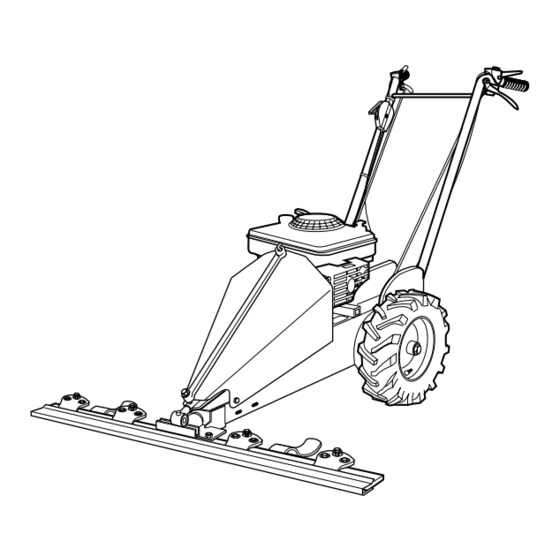
OWNER'S MANUAL
Sickle Bar Mowers
Safety
•
Assembly
•
Controls and Features
•
Operation
•
Maintenance
•
Parts List
•
GARDEN WAY INCORPORATED
Advertisement
Table of Contents
Troubleshooting


Need help?
Do you have a question about the 34061 and is the answer not in the manual?
Questions and answers