
Related Manuals for Kramer VP-23DS


Summary of Contents for Kramer VP-23DS
- Page 1 Kramer Electronics, Ltd. USER MANUAL Model: VP-23DS Presentation Switcher / Scaler...
-
Page 2: Table Of Contents
VP-23DS Communication Protocol Figures Figure 1: VP-23DS Presentation Switcher / Scaler Figure 2: Connecting the VP-23DS Presentation Switcher / Scaler Figure 3: Connecting a PC without using a Null-modem Adapter Figure 4: Setting the DIP to Flash Program Figure 5: Splash Screen Figure 6: Atmel –... - Page 3 Contents Tables Table 1: Front Panel VP-23DS Presentation Switcher / Scaler Features Table 2: Rear Panel VP-23DS Presentation Switcher / Scaler Features Table 3: Technical Specifications of the VP-23DS Presentation Switcher Table 4: VP-23DS Hex Table Table 5: VP-23DS Master Audio Selector Hex Table...
-
Page 4: Introduction
GROUP 6: Accessories and Rack Adapters; GROUP 7: Scan Converters and Scalers; and GROUP 8: Cables and Connectors 2 Downloadable from our Web site at http://www.kramerelectronics.com 3 Download up-to-date Kramer user manuals from our Web site at http://www.kramerelectronics.com 4 The complete list of Kramer cables is on our Web site at http://www.kramerelectronics.com... - Page 5 Getting Started KRAMER: SIMPLE CREATIVE TECHNOLOGY...
-
Page 6: Overview
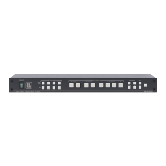
Kramer VP-23DS away from moisture, excessive sunlight and dust Your VP-23DS Presentation Switcher / Scaler Figure 1 illustrates the front and rear panels of the VP-23DS. Tables 1 and 2 define the front and rear panels of the VP-23DS, respectively. -
Page 8: Table 1: Front Panel Vp-23Ds Presentation Switcher / Scaler Features
Your VP-23DS Presentation Switcher / Scaler Table 1: Front Panel VP-23DS Presentation Switcher / Scaler Features Feature Function POWER Switch Illuminated switch for turning the unit ON or OFF SCALER MODE - FOLLOW Press so that the scaler output will follow the last... -
Page 9: Table 2: Rear Panel Vp-23Ds Presentation Switcher / Scaler Features
Your VP-23DS Presentation Switcher / Scaler Table 2: Rear Panel VP-23DS Presentation Switcher / Scaler Features Feature Function CV IN RCA Connectors Connect to the composite video sources (from IN 1 to IN 2) YC IN 4p Connectors Connect to the s-Video sources (from IN 1 to IN 2) -
Page 10: Installing The Vp-23Ds On A Rack
The machine is earthed (grounded) in a reliable way and is connected only to an electricity socket with If you are using a Kramer rack adapter grounding. Pay particular attention to situations where kit (for a machine that is not 19"), see... -
Page 11: Connecting The Vp-23Ds Presentation Switcher / Scaler
2 You do not need to connect all the inputs 3 Switch OFF the power on each device before connecting it to your VP-23DS. After connecting your VP-23DS, switch on its power and then switch on the power on each device. Switching on the VP-23DS, recalls the previous setup from the non-... -
Page 12: Figure 2: Connecting The Vp-23Ds Presentation Switcher / Scaler
6.1). 8. Connect the power cord (not shown in Figure 2). Figure 2: Connecting the VP-23DS Presentation Switcher / Scaler 1 Use the DYN / COND MIC switch (on the rear panel) to select a dynamic microphone or a condenser... -
Page 13: Connecting A Pc
Connecting the VP-23DS Presentation Switcher / Scaler 6.1 Connecting a PC You can connect a PC (or other controller) to the VP-23DS via the RS-232 port. To connect using the Null-modem adapter provided with the machine (recommended method): Connect the RS-232 DB9 rear panel port on the VP-23DS to the... -
Page 14: Operating The Vp-23Ds Presentation Switcher / Scaler
Operating the VP-23DS Presentation Switcher / Scaler Operating the VP-23DS Presentation Switcher / Scaler You can operate your VP-23DS via: The front panel buttons RS-232 serial commands transmitted by a touch screen system, PC, or other serial controller The front panel buttons include the:... -
Page 15: Operating The Scaler Section
Operating the VP-23DS Presentation Switcher / Scaler When setting the master audio gain to its minimum, the MUTE button illuminates. When MIX is OFF, then the microphone signal is not available at the master audio output. When MIX is ON and MUTE is OFF, the microphone signal is mixed with the master audio output. -
Page 16: Flash Memory Upgrade
3. Create a shortcut on your desktop to the file: “FLIP.EXE”. 8.2 Connecting the PC to the RS-232 Port Before installing the latest Kramer firmware version on a VP-23DS unit, do the following: 1. Disconnect the power on the VP-23DS. -
Page 17: Figure 5: Splash Screen
Figure 6: Atmel – Flip Window 3. Press the keyboard shortcut key F2 (or select the “Select” command from the Device menu, or press the integrated circuit icon in the upper right corner of the window). The “Device Selection” window appears: KRAMER: SIMPLE CREATIVE TECHNOLOGY... -
Page 18: Figure 7: Device Selection Window
Flash Memory Upgrade Figure 7: Device Selection Window 4. Click the button next to the name of the device and select from the list: AT89C51RD2: AT89C51RD2 T89C51RD2 Figure 8: Selecting the Device from the Selection Window 5. Click OK and select “Load Hex” from the File menu. -
Page 19: Figure 9: Loading The Hex
Figure 9: Loading the Hex 6. The Open File window opens. Select the correct HEX file that contains the updated version of the firmware for VP-23DS (for example, 23DSM_V1p2.hex) and click Open. 7. Press the keyboard shortcut key F3 (or select the “Communication / RS232”... -
Page 20: Figure 11: Atmel - Flip Window (Connected)
Flash Memory Upgrade Verify that in the Buffer Information column, the “HEX File: VP23DS.hex” appears. VP23DS.hex Figure 11: Atmel – Flip Window (Connected) 9. Click Run. After each stage of the operation is completed, the check-box for that stage becomes colored green When the operation is completed, all 4 check-boxes will be colored green and the status bar message: Memory Verify Pass appears 1 See also the blue progress indicator on the status bar... -
Page 21: Figure 12: Atmel - Flip Window (Operation Completed)
10. Close the “Atmel – Flip” window. 11. Disconnect the power on the VP-23DS. 12. Disconnect the RS-232 rear panel port on the VP-23DS unit from the Null-modem adapter. 13. On the rear panel, set the FLASH PROG DIP to normal... -
Page 22: Technical Specifications
10 selector buttons, master audio level, mic audio level, mix, lock, mute, RS-232 POWER SOURCE: 100-240V AC, 50/60Hz, (115V AC, U.S.A.) 7VA DIMENSIONS: 19-inch (W), 7-inch (D) 1U (H) rack-mountable WEIGHT: 2.6kg (8lbs.) approx ACCESSORIES: Power cord, Null modem adapter, Windows®-based Kramer control software 1 Specifications are subject to change without notice... -
Page 23: Hex Tables
18 82 81 81 Decrease 1 When controlling the VP-23DS via RS-232, refer to note 9 for command 42 in the communication protocol (see section 11) 2 For the microphone gain control, the second byte equals 82 KRAMER: SIMPLE CREATIVE TECHNOLOGY... -
Page 24: Vp-23Ds Communication Protocol
VP-23DS Communication Protocol 11 VP-23DS Communication Protocol The VS-23DS is compatible with Kramer’s Protocol 2000 (version 0.48) (below). This RS-232/RS-485 communication protocol uses four bytes of information as defined below. For RS-232, a null-modem connection between the machine and controller is used. The default data rate is 9600 baud, with no parity, 8 data bits and 1 stop bit. -
Page 25: Table 9: Instruction Codes
VP-23DS Communication Protocol Table 9: Instruction Codes INSTRUCTION DEFINITION FOR SPECIFIC INSTRUCTION NOTE DESCRIPTION INPUT OUTPUT RESET MACHINE SWITCH GROUPS 1-2 (1 – for CV group, 2 – for SV group) 3 – for VGA group 1 – from CV group 4 –... - Page 26 VP-23DS Communication Protocol NOTE 2 These are bi-directional definitions. That is, if the switcher receives the code, it will perform the instruction; and if the instruction is performed (due to a keystroke operation on the front panel), then these codes are sent. For example, if: 0000 0001 Instruction “...
- Page 27 VP-23DS Communication Protocol NOTE 9 When changing parameters (mix or gain), further information needed in instructions 22 and 25 is sent using instruction 42 – which is sent prior to the instruction. For example, to request the audio gain value of the master audio output...
- Page 28 EXCLUSION OF DAMAGES The liability of Kramer for any effective products is limited to the repair or replacement of the product at our option. Kramer shall not be liable for: 1. Damage to other property caused by defects in this product, damages based upon inconvenience, loss of use of the product, loss of time, commercial loss;...
- Page 29 For the latest information on our products and a list of Kramer distributors, visit our Web site: www.kramerelectronics.com, where updates to this user manual may be found. We welcome your questions, comments and feedback. Safety Warning: Disconnect the unit from the power supply before opening/servicing.
Need help?
Do you have a question about the VP-23DS and is the answer not in the manual?
Questions and answers