Table of Contents
Advertisement
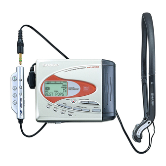
Illustration: MD-SR50H/SR50W
Illustration: MD-SR60E/SR60W
SAFETY PRECAUTION FOR SERVICE MANUAL ............................................................................................................... 2
SPECIFICATIONS ................................................................................................................................................................. 3
NAMES OF PARTS ............................................................................................................................................................... 4
OPERATION MANUAL .......................................................................................................................................................... 5
DISASSEMBLY ...................................................................................................................................................................... 8
REMOVING AND REINSTALLING THE MAIN PARTS ......................................................................................................... 9
ADJUSTMENT ...................................................................................................................................................................... 10
NOTES ON SCHEMATIC DIAGRAM .................................................................................................................................. 23
TYPES OF TRANSISTOR AND DIODE .............................................................................................................................. 23
VOLTAGE ............................................................................................................................................................................ 24
BLOCK DIAGRAM ............................................................................................................................................................... 25
SCHEMATIC DIAGRAM ...................................................................................................................................................... 26
WIRING SIDE OF P.W.BOARD ........................................................................................................................................... 28
WAVEFORMS OF MD CIRCUIT ......................................................................................................................................... 31
TROUBLESHOOTING ......................................................................................................................................................... 32
FUNCTION TABLE OF IC .................................................................................................................................................... 35
PARTS GUIDE/EXPLODED VIEW
SERVICE MANUAL
CONTENTS
SHARP CORPORATION
- 1 -
MD-SR50H/50W/60E/60W
MD-SR50H(BL)
MD-SR50H(S)
MD-SR50H(YR)
MD-SR50W(BL)
MD-SR50W(S)
MD-SR60E(GL)
MD-SR60W(S)
• In the interests of user-safety the set should be restored to its
original condition and only parts identical to those specified be
used.
This document has been published to be used
for after sales service only.
The contents are subject to change without notice.
No. S2006MDSR50H/
Page
Advertisement
Table of Contents

Related Manuals for Sharp MD-SR50HBL


Summary of Contents for Sharp MD-SR50HBL
-
Page 1: Table Of Contents
FUNCTION TABLE OF IC ..............................35 PARTS GUIDE/EXPLODED VIEW PACKING METHOD (MD-SR50H for U.K./SR60E Only) This document has been published to be used SHARP CORPORATION for after sales service only. The contents are subject to change without notice. – 1 –... -
Page 2: Safety Precaution For Service Manual
MD-SR50H/50W/60E/60W SAFETY PRECAUTION FOR SERVICE MANUAL Precaution to be taken when replacing and servicing the Laser Pickup. The AEL (Accessible Emission Level) of Laser Power Output for this model is specified to be lower than Class I Requirements. However, the following precautions must be observed during servicing to protect your eyes against exposure to the laser beam. (1) When the cabinet has been removed, the power is turned on without a compact disc, and the Pickup is on a position outer than the lead-in position, the Laser will light for several seconds to detect a disc. -
Page 3: Specifications
MD-SR50H/50W/60E/60W FOR A COMPLETE DESCRIPTION OF THE OPERATION OF THIS UNIT, PLEASE REFER TO THE OPERATION MANUAL. SPECIFICATIONS The operation time when using an alkaline battery may be General different, depending on the type and manufacturer of the battery Power source: DC 5V : AC adaptor (AC 220-230V, 50/60 Hz) and on the operating temperature. -
Page 4: Names Of Parts
MD-SR50H/50W/60E/60W NAMES OF PARTS Remote control unit 1 2 3 4 5 6 1. Monaural Long-Play Mode Indicator 2. Record Indicator 3. Level Meter 4. Fast Play Indicator 5. Repeat Indicator 6. TOC Indicator 7. Battery Indicator 8. Random Indicator 9. -
Page 5: Operation Manual
MD-SR50H/50W/60E/60W OPERATION MANUAL – 5 –... - Page 6 MD-SR50H/50W/60E/60W – 6 –...
- Page 7 MD-SR50H/50W/60E/60W – 7 –...
-
Page 8: Disassembly
MD-SR50H/50W/60E/60W DISASSEMBLY Cares before disassembling When assembling the machine after disassembling or (B1)x2 repair, observe the following requirements so as to ensure ø1.4x2mm safety and performance. Top Cabinet 1. Remove the batteries from the machine, and take out the mini-disc. (A1)x2 (A1)x2 ø1.4x2mm... -
Page 9: Removing And Reinstalling The Main Parts
MD-SR50H/50W/60E/60W REMOVING AND REINSTALLING THE MAIN PARTS Remove the mechanism according to the disassembling meth- (A2)x3 ods 1 to 4. (See Page 8.) ø1.4x2.8mm Spindle Mechanism Flexible How to remove the spindle motor (See Fig. 9-1.) Motor PWB Solder joint 1. -
Page 10: Adjustment
MD-SR50H/50W/60E/60W ADJUSTMENT Test disc MD adjustment needs two types of disc, namely recording disc (low reflection disc) and playback-only disc (high reflection disc). Parts No. Type Test disc High reflection disc MMD-110 (TEAC Test MD) 88GMMD-110 Low reflection disc MMD-212 (TEAC Test MD) 74-minute disc 88GMMD-212 Low reflection disc MMD-213A (TEAC Test MD) 80-minute disc... - Page 11 MD-SR50H/50W/60E/60W Operation in each TEST mode 1. AUTO1 Mode • When the STOP button is pressed while the AUTO1 menu appears or during automatic adjustment, the mode changes to the TEST mode stop state. At this time the adjustment value is not output. •...
- Page 12 MD-SR50H/50W/60E/60W 5. NORMAL Mode • When the STOP button is pressed while the NORMAL menu appears, the mode changes to the TEST mode stop state. • Indication during operation Indication of memory capacity on main unit LCD [ ] + Level meter : Internal mode : Address (Cluster section) : Address (Sector section)
- Page 13 MD-SR50H/50W/60E/60W EEPROM (IC402) writing procedure 1. Procedure to replace EEPROM and write initial value of microcomputer in EEPROM (1) Replace EEPROM. (2) Refer to the latest EEPROM data list. (3) Press the Display button, ENTER button and Play button to start the test mode. (4) Version display [ V e r .
- Page 14 MD-SR50H/50W/60E/60W EEPROM DATA LIST (EEPROM version b) TEMP setting Sled setting Item display Set values Item display Set values T M _ _ Calculate values S L G _ S L 2 _ S L M _ Fucus setting S L V _ Item display Set values S K k _...
- Page 15 MD-SR50H/50W/60E/60W – 15 –...
- Page 16 MD-SR50H/50W/60E/60W – 16 –...
- Page 17 MD-SR50H/50W/60E/60W – 17 –...
- Page 18 MD-SR50H/50W/60E/60W – 18 –...
- Page 19 MD-SR50H/50W/60E/60W – 19 –...
- Page 20 MD-SR50H/50W/60E/60W – 20 –...
- Page 21 MD-SR50H/50W/60E/60W – 21 –...
- Page 22 MD-SR50H/50W/60E/60W – 22 –...
-
Page 23: Notes On Schematic Diagram
MD-SR50H/50W/60E/60W NOTES ON SCHEMATIC DIAGRAM • Resistor: • The indicated voltage in each section is the one measured To differentiate the units of resistors, such symbol as K and by Digital Multimeter between such a section and the chas- M are used: the symbol K means 1000 ohm and the symbol sis with no signal given. -
Page 24: Voltage
MD-SR50H/50W/60E/60W VOLTAGE IC101 IC201 IC601 IC353 IC401 IC501 VOLTAGE PIN VOLTAGE PIN VOLTAGE VOLTAGE VOLTAGE VOLTAGE VOLTAGE VOLTAGE 0.71V 0.84V 2.73V 2.34V 0.71V 2.48V — — 0.71V 1.22V — 2.35V 0.29V — 0.71V — 2.32V 1.24V 1.24V — 2.32V — 2.49V 1.24V 1.24V... -
Page 25: Block Diagram
MD-SR50H/50W/60E/60W J702 MIC IN (READY FOR J801 J703 J703 Ni - MH Battery PLUG/IN DC IN J701 J701 HEADPHONES REMOTE (4~5.5V) POWER) OPTICAL IN LINE IN LINE CONTROL Dry Battery (1 pieces) 1.0-1.7V +1-2V Figure 25 BLOCK DIAGRAM – 25 –... -
Page 26: Schematic Diagram
MD-SR50H/50W/60E/60W C112 C209 0.033 MAIN PWB-A 22P (CH) C111 C110 0.0033 C109 C107 TP139 0.22 0.012 C106 PLAYBACK SIGNAL 0.22 N.C. RECORD SIGNAL XL201 R106 ROUT EFMAGI ADAGC 33.868MHz ADIPI ADIPO DIFF N.C. C204 LDCNT1 C102 IC202 DIFF ADLPFO 0.47 C212 N.C. - Page 27 MD-SR50H/50W/60E/60W TP451 DISPLY R457 TP452 EDIT R455 TP453 P-MODE 5.6K R458 HKEY2 TP454 BASS DADATA R456 TP455 SKIP UP 8.2K TP456 VOL DOWN ADDATA R454 HKEY1 TP457 VOL UP DFCK BCLK TP458 ENTER R451 R452 R453 TP459 SKIP DOWN LRCK 5.6K 8.2K TP460...
-
Page 28: Wiring Side Of P.w.board
MD-SR50H/50W/60E/60W PWB-A(TOP VIEW) R296 HOLD Q250 C252 SW402 D251 R291 R293 BATTERY IC257 R253 TERMINAL,+ IC251 TP803 R292 R251 D281 R252 R257 Q251 TP171 IC255 TP106 C291 R255 R250 C454 C171 TP441 TP100 R272 C254 R464 R279 C172 L171 IC256 R271 IC258 CK112... - Page 29 MD-SR50H/50W/60E/60W PWB-A(BOTTOM VIEW) R841 C846 C848 C841 C847 F841 D842 C844 R850 R844 IC842 C845 SW403 R818 LID DETECTION C850 C202 IC841 C833 D831 L841 D832 IC202 C100 C842 C821 C835 D841 R202 L821 C843 C201 C354 C353 L100 CK222 R161 L200 C165...
- Page 30 MD-SR50H/50W/60E/60W Magnetic Head Flexible PWB (23) M901 Spindle Motor Optical Pickup Unit (15) Magnetic Head (21) SW902 Disc Protect Mechanism Flexible PWB (8) PH901 CN601 Photo To Main PWB Interrupter P28 1-E M902 CN101 Sled Motor To MAIN PWB P28 1-C M903 To MAIN PWB Lift Motor...
-
Page 31: Waveforms Of Md Circuit
MD-SR50H/50W/60E/60W WAVEFORMS OF MD CIRCUIT Stopped 1994 / 12 / 15 22:54:19 Stopped 1994 / 12 / 16 00:24:17 Stopped 1994 / 12 / 16 01:03:40 CH1=1mV CH2=500mV CH3=5V CH4=2V 50ms/div CH1=2V CH2=2V CH3=2V CH4=2V 50us/div CH1=1V CH2=2V CH3=500mV 2ms/div DC 10:1 DC 10:1 DC 10:1... -
Page 32: Troubleshooting
MD-SR50H/50W/60E/60W TROUBLESHOOTING It is advisable to use the TEST mode (refer to Error Data Display Mode, P19) indicating the causes of troubles before starting repair. Causes of operation errors (up to 10 errors) are recorded as error codes. This information is useful for repair. - Page 33 MD-SR50H/50W/60E/60W • Abnormal display Is waveform output from CN482 pins 6 to 8? Is waveform output from IC401 pins 9,11,13? Are the pin 4 (VCC) and pin 5 (GND) normal? Check between IC401 and Check the periphery of IC401. CN482. Check for pattern breakage of flexible PWB, check for defects of display microcomputer (replace the display unit).
- Page 34 MD-SR50H/50W/60E/60W • The spindle motor fails to run.Does the head move Check the IC201 periphery. Does the waveform appear on the IC201 pins 24 and 25 after TEST mode AUTO2 completion and in this state? Replace. IC601 Does waveform appear on the IC601 pin 43? Does waveform appear on IC901 pins 1, 2 and 23? L608, IC201, IC901, CN601 and flex, etc.
-
Page 35: Function Table Of Ic
MD-SR50H/50W/60E/60W FUNCTION TABLE OF IC IC401 RH-iX0341AWZZ: System Microcomputer (IX0341AW) (1/3) Terminal Name Input/Output Pin No. Port Name Function P12/TCLKA Input Track cross signal/focus drive detection TCLKB SPIN Input Spindle motor FG pulse detection input INNSW Input Mechanism inner SW position detection input DISCPR Input Disc record inhibition switch input... - Page 36 MD-SR50H/50W/60E/60W IC401 RH-iX0341AWZZ: System Microcomputer (IX0341AW) (2/3) Terminal Name Input/Output Pin No. Port Name Function Input Operation mode selection input 1 _PLAY Input Unit PLAY button operation detection input WDTOVF WDTOVF Output Watch dog timer (not used) Input Operation mode selection input 2 _RESET Input Microcomputer hard reset input...
- Page 37 MD-SR50H/50W/60E/60W IC401 RH-iX0341AWZZ: System Microcomputer (IX0341AW) (3/3) System LSI expansion output port (6th generation: LR37811) Terminal Name Input/Output Pin No. Port Name Function Remarks EXPORT0 LDCNT1 Output Recording head raising-lowering control output 1 See the separate table *3. EXPORT1 LDCNT2 Output Recording head raising-lowering control output 2 See the separate table *3.
- Page 38 MD-SR50H/50W/60E/60W — M E M O — – 38 –...
- Page 39 “HOW TO ORDER REPLACEMENT PARTS” To have your order filled promptly and correctly, please furnish the For U.S.A. only following information. Contact your nearest SHARP Parts Distributor to order. 1. MODEL NUMBER 2. REF. No. 3. PART NO. 4. DESCRIPTION For location of SHARP Parts Distributor, Please call Toll-Free;...
- Page 40 MD-SR50H/50W/60E/60W PRICE PRICE PARTS CODE DESCRIPTION PARTS CODE DESCRIPTION RANK RANK INTEGRATED CIRCUITS COILS IC101 VHIIR3R55//-1 AQ RF Signal Processor,IR3R55 L100 VPBNN100K0000 AC 10 H IC201 VHILR37811/-1 BB ENDEC/SERVO/ATRAC, L171 RCILC0356AFZZ AC 10 H LR37811 L491 VRS-TV2AB330J AA 33 ohms,1/10W IC202 RH-IX2567AFZZ BA 4M D-RAM,IX2567AF...
- Page 41 MD-SR50H/50W/60E/60W PRICE PRICE DESCRIPTION PARTS CODE DESCRIPTION PARTS CODE RANK RANK C704 VCSATE0JJ476M AD 47 F,6.3V,Electrolytic,Tantalum R255 VRS-CY1JB472J AA 4.7 kohms,1/16W C711,712 VCCCCY1HH101J AA 100 pF (CH),50V R256 VRS-CY1JB563J AA 56 kohms,1/16W C713,714 VCKYTV1AB105K AD 1 F,10V R257 VRS-CY1JB273D AA 27 kohms,1/16W C715 VCKYCY1CB104K AB 0.1 F,16V...
- Page 42 MD-SR50H/50W/60E/60W PRICE PRICE DESCRIPTION PARTS CODE PARTS CODE DESCRIPTION RANK RANK R801 VHHSMDM110V-1 AK Conductive Resin Switch RCILH0002AWZZ Magnetic Head R802 VRS-CY1JB561J AA 560 ohms,1/16W PCOVP1339AFZZ AD Cover,Mechanism R803 VRS-CY1JB122J AA 1.2 kohms,1/16W QPWBH0338AFZZ J AH Magnetic Head Flexible PWB R806 VRS-CY1JB563J AA 56 kohms,1/16W...
- Page 43 MD-SR50H/50W/60E/60W PRICE PRICE DESCRIPTION PARTS CODE DESCRIPTION PARTS CODE RANK RANK P.W.B. ASSEMBLY (Not Replacement Item) MSPRP0032AWFW J AB Spring A,Cartridge LHLDZ3012AWM1 AF Main Frame Ass’y MSPRP0034AWFW J AB Spring C,Cartridge PWB-A 92LPWB3355MDSS J — Main PCUSZ0021AWZZ J Cushion,Display Bracket OTHER SERVICE PARTS PSPAP0002AW00 Spacer,Top Cabinet...
- Page 44 MD-SR50H/50W/60E/60W 502x2 508x2 (PH901) (SW902) 505x3 M901 M903 503x2 M902 Figure 5 MD MECHANISM EXPLODED VIEW – 5 –...
- Page 45 MD-SR50H/50W/60E/60W MD MECHANISM 225x2 601x2 PWB-A 605x4 601x2 601x2 Figure 6 CABINET EXPLODED VIEW – 6 –...
-
Page 46: Packing Method (Md-Sr50H For U.k./Sr60E Only)
MD-SR50H/50W/60E/60W PACKING METHOD (MD-SR50H FOR U.K./SR60E ONLY) TINSE0290AWZZ Operation Manual Setting position of switches and knobs [SR50H for U.K.] UNIT HOLD SPAKZ0490AWZZ Operation Manual Spacer Remote Control HOLD CANCEL UBAGC0006AWSA Carrying Case SPAKC0945AWZZ Packing Case [SR60E] SPAKC0970AWZZ Packing Case RPHOH0005AWZZ Earphones [SR60E Only] [SR50H-S for U.K.] RPHOH0001AWZZ... - Page 47 MD-SR50H/50W/60E/60W — M E M O — – 8 –...
- Page 48 MD-SR50H/50W/60E/60W © COPYRIGHT 2000 BY SHARP CORPORATION ALL RIGHTS RESERVED. No part of this publication may be reproduced, stored in a retrieval system, or transmitted in any from or by any means, electronic, mechanical, photocopying, recording, or otherwise, without prior written permission of the publisher.