Qlogic SANbox 1400 Series Quick Start Manual
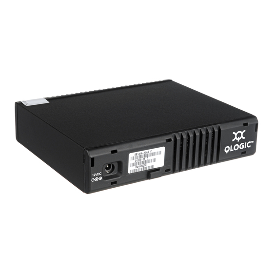
Fibre channel switch
Hide thumbs
Also See for SANbox 1400 Series:
- User manual (278 pages) ,
- Installation manual (214 pages) ,
- Supplementary manual (12 pages)

Related Manuals for Qlogic SANbox 1400 Series


Summary of Contents for Qlogic SANbox 1400 Series
-
Page 1: Quick Start Guide
Quick Start Guide F I B R E C H A N N E L S W I T C H I N S T A L L A T I O N ® S A N b o x 1 4 0 0 S e r i e s ®... - Page 2 Technical Support can be reached by the following methods: http://support.qlogic.com E-mail support@qlogic.com The QLogic knowledge database contains troubleshooting information for the QLogic HBAs. Access the data base from the QLogic Support Web page, http://support.qlogic.com. Use the Support Center search engine to look for specific troubleshooting information.
-
Page 3: Installation Instructions
For a surface mount, attach the rubber feet to the locations on the bottom of the switch. ❑ For a rack mount, install the SANbox 1400 Series rail kit in a standard 19" rack as described in the SANbox 1400 Series Fibre Channel Switch Rack Mounting Guide that is packaged with the rail kit. - Page 4 Step 4. Apply Power to the Switch HEARTBEAT ❑ Connect the external DC power supply to the back of the switch. SYSTEM INPUT ❑ FAULT POWER Attach the AC power cord to the external power supply and wall outlet or power strip. Verify that the Input Power LED is illuminated.
- Page 5 Step 9. Connect Devices and Switches ❑ Connect fibre optic cables between the installed SFP transceivers and their corresponding devices. Each port auto-negotiates the proper port type with the connected device or switch. Congratulations! ® You have successfully installed your QLogic SANbox 1400 Series Switch!
- Page 7 © 2008 QLogic Corporation. QLogic, the QLogic logo, SANbox, and SANsurfer Switch Manger are registered trademarks or trademarks of QLogic Corporation. MacOS X is a registered trademarks of Apple Computer, Inc. Linux is a registered trademark of Linus Torvalds. Windows, Microsoft, and Internet Explorer are registered trademarks of Microsoft Corporation.
- Page 8 *50638-01 QLogic Corporation 26650 Aliso Viejo Parkway Aliso Viejo, CA 92656 949.389.6000 www.qlogic.com 50638-01 C...
Need help?
Do you have a question about the SANbox 1400 Series and is the answer not in the manual?
Questions and answers