Table of Contents
Advertisement
Quick Links
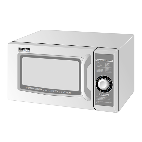
1000 W/ R-21J CA
BEFORE SERVICING ...................................................................................................... INSIDE FRONT COVER
WARNING TO SERVICE PERSONNEL ................................................................................................................ 1
MICROWAVE MEASUREMENT PROCEDURE ................................................................................................... 2
FOREWORD AND WARNING ............................................................................................................................... 3
PRODUCT SPECIFICATIONS .............................................................................................................................. 4
GENERAL INFORMATION ................................................................................................................................... 4
OPERATION .......................................................................................................................................................... 6
TROUBLESHOOTING GUIDE .............................................................................................................................. 9
TEST PROCEDURE ............................................................................................................................................ 10
TOUCH CONTROL PANEL ................................................................................................................................. 16
COMPONENT REPLACEMENT AND ADJUSTMENT PROCEDURE ................................................................ 20
PICTORIAL DIAGRAM ........................................................................................................................................ 27
CONTROL PANEL CIRCUIT .............................................................................................................................. 28
PRINTED WIRING BOARD ................................................................................................................................. 29
PARTS LIST ........................................................................................................................................................ 30
PACKING AND ACCESSORIES ......................................................................................................................... 34
SHARP CORPORATION
SERVICE MANUAL
MODEL
TIME GUIDE FOR ONE
SERVI NG
15 - 30 sec.
30 - 60 sec.
Bagel, Roll
Hot Dog
Muffin, Pastry
Pizza Slice
Pie Slice
Small Sandwic h
1 - 2 min.
2 - 3 min.
Beverag e, Soup
Cassero le, Stew
Large Sandwic h
Chili, Chowde r
Popcorn , 1.5 oz.
Popcorn , 3.5 oz.
1
40 50
1.5
30
F
E
G
D
H
20
C
I
B
2
In the interest of user-safety the oven should be restored to its original
10
J
A
0
K
2.5
L
M
N
3
condition and only parts identical to those specified should be used.
O
T
S
P
6
R
Q
4
5
INST RUC TION
S
WARNING TO SERVICE PERSONNEL: Microwave ovens contain
With the door
close d,turn the
the desir ed
timer to
time. Oven
will begin
opera ting imme
diate ly.
To shut oven
off manu ally,r
to "0".
eturn timer
circuitry capable of producing very high voltage and current,
contact with following parts may result in a severe, possibly fatal,
electrical shock. (High Voltage Capacitor, High Voltage Power
Transformer, Magnetron, High Voltage Rectifier Assembly, High
Voltage Harness etc..)
TABLE OF CONTENTS
LIGHT DUTY
COMMERCIAL
MICROWAVE OVENS
R-21JCA-F
This document has been published to be used for after
sales service only.
The contents are subject to change without notice.
R-21JCA-F
S0514R21JCPAF
Page
Advertisement
Table of Contents

Related Manuals for Sharp R-21JCA-F


Summary of Contents for Sharp R-21JCA-F
-
Page 1: Table Of Contents
R-21JCA-F SERVICE MANUAL S0514R21JCPAF LIGHT DUTY COMMERCIAL MICROWAVE OVENS R-21JCA-F MODEL 1000 W/ R-21J CA TIME GUIDE FOR ONE SERVI NG 15 - 30 sec. 30 - 60 sec. Bagel, Roll Hot Dog Muffin, Pastry Pizza Slice Pie Slice Small Sandwic h 1 - 2 min. -
Page 2: Precautions To Be Observed Before And During Servicing To Avoid Possible Exposure To Excessive Microwave Energy
Before servicing an operative unit, perform a microwave emission check as per the Microwave Measurement Procedure outlined in this service manual. If microwave emissions level is in excess of the specified limit, contact SHARP ELECTRONICS CORPORATION immediately @1-800-237-4277. If the unit operates with the door open, service person should 1) tell the user not to operate the oven and 2) contact SHARP ELECTRONICS CORPORATION and the Food and Drug Administration's Center for Devices and Radiological Health immediately. -
Page 3: Warning To Service Personnel
R-21JCA-F WARNING TO SERVICE PERSONNEL Microwave ovens contain circuitry capable of pro- ducing very high voltage and current, contact with following parts may result in a severe, possibly fatal, electrical shock. (Example) High Voltage Capacitor, High Voltage Power Trans- former, Magnetron, High Voltage Rectifier Assem- bly, High Voltage Harness etc.. -
Page 4: Microwave Measurement Procedure
R-21JCA-F MICROWAVE MEASUREMENT PROCEDURE A. Requirements: 1) Microwave leakage limit (Power density limit): The power density of microwave radiation emitted by a microwave oven should not exceed 1mW/cm at any point 5cm or more from the external surface of the oven, measured prior to acquisition by a... -
Page 5: Foreword And Warning
MICROWAVE OVEN GENERAL INFORMATION R-21JCA-F FOREWORD This Manual has been prepared to provide Sharp Electronics Corp. OPERATION Service Personnel with Operation and Service Information for the SHARP MICROWAVE OVENS, R-21JCA-F. It is recommended that service personnel carefully study the entire text of... -
Page 6: Product Specifications
R-21JCA-F SPECIFICATION ITEM DESCRIPTION Power Requirements 120 Volts 14 Amperes 60 Hertz / Single phase, 3 wire grounded Power Output 1000 watts (IEC 705 Test Procedure) Operating frequency of 2450MHz Case Dimensions Width 20-1/2" (520mm) Height 12-1/8" (309mm) Depth 16"... -
Page 7: Oven Diagram
R-21JCA-F OVEN DIAGRAM 1. Back splash cover 2. Side splash cover 3. Oven light 4. Ceramic shelf 5. Control panel 6. Cavity face plate 7. Door latch openings 8. Door latches 9. Door hinges 10. Door seals and sealing surfaces 11. -
Page 8: Operation
R-21JCA-F OPERATION DESCRIPTION OF OPERATING SEQUENCE The following is a description of component functions during 5. Upon completion of the cooking time, the power transformer, oven operation. oven lamp, etc. are turned off, and the generation of microwave energy is stopped. The oven will revert to the OFF CONDITION OFF condition. - Page 9 R-21JCA-F SCHEMATIC NOTE: Indicates components with potential above 250 V. NOTE: CONDITION OF OVEN 1. LIGHT UP DIAL OFF. 2. DOOR CLOSED. THERMAL THERMAL CUT-OUT CUT-OUT NOISE FILTER 125˚C (OVEN) 145˚C (MAG.) POWER TRANSFORMER AC120V 60 Hz CAPACITOR 0.94 µF...
-
Page 10: Description And Function Of Components
R-21JCA-F DESCRIPTION AND FUNCTION OF COMPONENTS DOOR OPEN MECHANISM and secondary interlock switch contacts fail to open, the The door is opened by grasping the door handle, refer to Figure monitor fuse blows simultaneously with closing of the D-1. monitor switch contacts. -
Page 11: Troubleshooting Guide
R-21JCA-F TROUBLESHOOTING GUIDE Never touch any part in the circuit with your hand or an uninsulated tool while the power supply is connected. When troubleshooting the microwave oven, it is helpful to follow the Sequence of Operation in performing the checks. Many of the possible causes of trouble will require that a specific test be performed. -
Page 12: Test Procedure
R-21JCA-F TEST PROCEDURES PROCEDURE COMPONENT TEST LETTER MAGNETRON ASSEMBLY TEST 1. Disconnect the power supply cord, and then remove outer case. 2. Open the door and block it open. 3. Discharge high voltage capacitor. 4. To test for an open filament, isolate the magnetron from the high voltage circuit. A continuity check across the magnetron filament leads should indicate less than 1 ohm. - Page 13 R-21JCA-F TEST PROCEDURES PROCEDURE COMPONENT TEST LETTER HIGH VOLTAGE RECTIFIER TEST 1. Disconnect the power supply cord, and then remove outer case. 2. Open the door and block it open. 3. Discharge high voltage capacitor. 4. Isolate the rectifier from the circuit. Using the highest ohm scale of the meter, read the resistance across the terminals and observe, reverse the leads to the rectifier terminals and observe meter reading.
- Page 14 R-21JCA-F TEST PROCEDURES PROCEDURE COMPONENT TEST LETTER SECONDARY INTERLOCK SWITCH TEST 1. Disconnect the power supply cord, and then remove outer case. 2. Open the door and block it open. 3. Discharge high voltage capacitor. 4. Isolate the switch and connect the ohmmeter to the common (COM.) and normally open (NO) terminal of the switch.
- Page 15 R-21JCA-F TEST PROCEDURES PROCEDURE COMPONENT TEST LETTER BLOWN MONITOR FUSE TEST 1. Disconnect the power supply cord, and then remove outer case. 2. Open the door and block it open. 3. Discharge high voltage capacitor. 4. If the monitor fuse is blown when the door is opened, check the primary interlock relay, secondary interlock switch and monitor switch according to the "TEST PROCEDURE"...
- Page 16 R-21JCA-F TEST PROCEDURES PROCEDURE COMPONENT TEST LETTER 6) After that procedure, re-connect the power supply cord. 1. Control Panel The following symptoms indicate a defective control unit. 1-1 In connection with LEDs a) At a certain LED, all or some LEDs do not light up.
- Page 17 R-21JCA-F TEST PROCEDURES PROCEDURE COMPONENT TEST LETTER FOIL PATTERN ON THE PRINTED WIRING BOARD TEST To protect the electronic circuits, this model is provided with a fine foil pattern added to the primary on the PWB, this foil pattern acts as a fuse.
-
Page 18: Touch Control Panel
R-21JCA-F TOUCH CONTROL PANEL ASSEMBLY OUTLINE OF TOUCH CONTROL PANEL Control Unit 4) Reset Circuit Control unit consists of LSI, power source circuit, synchroniz- A circuit to generate a signals which resets the LSI to the ing signal circuit, reset circuit, buzzer circuit, encoder circuit initial state when power is supplied. - Page 19 R-21JCA-F Pin No. Signal Description Auto clear terminal. RESET Signal is input to reset the LSI to the initial state when power is applied. Temporarily set to "L" level the moment power is applied, at this time the LSI is reset. Thereafter set at "H"...
- Page 20 R-21JCA-F TOUCH CONTROL PANEL SERVICING 1. Precautions for Handling Electronic Components panel while keeping it connected to the oven. This unit uses CMOS LSI in the integral part of the circuits. B. On some models, the power supply cord between the touch...
- Page 21 R-21JCA-F PRECAUTIONS FOR USING LEAD-FREE SOLDER 1. Employing lead-free solder The "Main PWB" of this model employs lead-free solder. This is indicated by the "LF" symbol printed on the PWB and in the service manual. The suffix letter indicates the alloy type of the solder.
-
Page 22: Component Replacement And Adjustment Procedure
4. If the outer case (cabinet) is not fitted. 4. The door is bent or warped. WARNING FOR WIRING To prevent an electric shock, take the following precau- 3) Sharp edge: tions. Bottom plate, Oven cavity, Waveguide flange, Chassis 1. Before wiring, support and other metallic plate. -
Page 23: Magnetron Removal
R-21JCA-F HIGH VOLTAGE RECTIFIER ASSEMBLY AND HIGH VOLTAGE CAPACITOR REMOVAL To remove the components, proceed as follows. 9. Remove one (1) screw holding the capacitor holder to the 1. Disconnect the power supply cord and then remove outer oven cavity rear plate. -
Page 24: Antenna Motor Removal
R-21JCA-F ® POSITIVE LOCK CONNECTOR (NO-CASE TYPE) REMOVAL Terminal 1. Disconnect the power supply cord and then remove outer case. Positive lock® connector 2. Open the door and block it open. 3. Discharge high voltage capacitor. Push ® 4. Push the lever of positive lock connector. -
Page 25: Power Supply Cord Replacement
R-21JCA-F POWER SUPPLY CORD REPLACEMENT Removal 7. Now, the power supply cord is free. 1. Disconnect the power supply cord and then remove outer case. Re-install 2. Open the door and block it open. 1. Insert the moulding cord stopper of power supply cord into 3. -
Page 26: Door Parts Removal
R-21JCA-F After adjustment, check the following. 1. In and out play of door remains less than 0.5mm when in the Latch Head Handle latched position. First check upper position of latch hook, Lever pushing and pulling upper portion of door toward the oven Latch Hook face. -
Page 27: Pictorial Diagram
R-21JCA-F (B) An approved microwave survey meter should be used Upper to assure compliance with proper microwave radiation Oven emission limitation standards. (Refer to Microwave Hinge Measurement Procedure.) Upper Oven Hinge After any service, make sure of the following : 1. -
Page 28: Installation Of Ceramic Shelf
R-21JCA-F Flat face Antenna motor shaft Flat face Centre Antenna holder Hole Stirrer antenna assembly Stirrer antenna Stirrer antenna's big blade Antenna motor shaft Figure C-9. Derection of Antenna Motor Shaft and Oven cavity bottom plate Stirrer Antenna Assembly Antenna holder... - Page 29 R-21JCA-F...
-
Page 30: Control Panel Circuit
R-21JCA-F... -
Page 31: Printed Wiring Board
R-21JCA-F LD10 JP33 LD11 LD12 LD13 JP29 JP28 JP27 LD14 JP26 LD15 JP24 LD20 LD16 LD19 LD17 LD18 JP20 JP19 JP18 JP16 JP17 JP15 JP13 VRS1 Figure S-3. Printed Wiring Board... -
Page 32: Parts List
R-21JCA-F PARTS LIST ∆ Note: The parts marked “ ” may cause undue microwave exposure. The parts marked “*” are used in voltage more than 250V. REF. NO. PART NO. DESCRIPTION Q'TY CODE ELECTRIC PARTS 1- 1 FFS-BA015WRK0 Monitor fuse(20A) and monitor switch(V-5220D-070) assembly... - Page 33 To have your order filled promptly and correctly, please furnish the following information. 1. MODEL NUMBER 2. REF. NO. 3. PART NO. 4. DESCRIPTION Order Parts from the authorized SHARP parts Distributor for your area. Defective parts requiring return should be returned as indicated in the Service Policy.
- Page 34 R-21JCA-F OVEN AND CABINET PARTS 1-10 4-28 7-13 4-10 7-13 7-13 4-25 7-12 4-32 1-13 4-26 4-34 4-26 4-24 4-15 4-27 4-14 4-19 4-15 4-36 4-16 7-10 4-40 7-11 1-12 4-23 4-18 4-24 4-21 4-20 4-21 4-21 4-22 4-20 4-13...
- Page 35 R-21JCA-F CONTROL PANEL PARTS 3-2-1 3-2-2 DOOR PARTS 5-1-15 5-1-16 5-1-14 5-1-2 5-1-12 5-1-16 5-1-18 5-1-4-2 5-1-16 5-1-4-5 5-1-13 5-1-4-4 5-1-4 5-1-1 5-1-4-3 5-1-4-1 5-1-4-5 5-1-16 5-1-12 5-1-8 5-1-7 5-1-17 5-1-9 5-1-11 5-1-3 5-1-8 5-1-17 5-1-5 5-1-6 MISCELLANEOUS 5-1-10 Actual wire harness may be different from illustration.
-
Page 36: Packing And Accessories
No part of this publication may be reproduced, stored in retrieval systems, or transmitted in any form or by any means, electronic, me- chanical, photocopying, recording, or other- wise, without prior written permission of the publisher. '05 SHARP CORP. (10S0.80E) Printed in U.S.A...
Need help?
Do you have a question about the R-21JCA-F and is the answer not in the manual?
Questions and answers