
Related Manuals for Miller Electric Snap Start II


Summary of Contents for Miller Electric Snap Start II
- Page 1 OM-629 177 029C April 2000 TIG (GTAW) Welding Description High Frequency Arc Starter Snap Start II Visit our website at www.MillerWelds.com...
- Page 2 Welding Process Manuals such as SMAW, GTAW, GMAW, and GMAW-P. Miller Electric manufactures a full line of welders and welding related equipment. For information on other quality Miller products, contact your local Miller distributor to receive the latest full line catalog or individual catalog sheets.
-
Page 3: Table Of Contents
TABLE OF CONTENTS SECTION 1 – SAFETY PRECAUTIONS - READ BEFORE USING ......1-1. -
Page 5: Section 1 - Safety Precautions - Read Before Using
SECTION 1 – SAFETY PRECAUTIONS - READ BEFORE USING som _nd_4/98 1-1. Symbol Usage Means Warning! Watch Out! There are possible hazards with this procedure! The possible hazards are shown in the adjoining symbols. This group of symbols means Warning! Watch Out! possible Y Marks a special safety message. - Page 6 ARC RAYS can burn eyes and skin. BUILDUP OF GAS can injure or kill. D Shut off shielding gas supply when not in use. Arc rays from the welding process produce intense D Always ventilate confined spaces or use visible and invisible (ultraviolet and infrared) rays that can burn eyes and skin.
-
Page 7: Additional Symbols For Installation, Operation, And Maintenance
1-3. Additional Symbols For Installation, Operation, And Maintenance FIRE OR EXPLOSION hazard. MOVING PARTS can cause injury. D Do not install or place unit on, over, or near D Keep away from moving parts such as fans. combustible surfaces. D Keep all doors, panels, covers, and guards D Do not install unit near flammables. -
Page 8: Emf Information
1-5. EMF Information Considerations About Welding And The Effects Of Low Frequency 1. Keep cables close together by twisting or taping them. Electric And Magnetic Fields 2. Arrange cables to one side and away from the operator. Welding current, as it flows through welding cables, will cause electro- magnetic fields. -
Page 9: Section 1 - Consignes De Securite - Lire Avant Utilisation
SECTION 1 – CONSIGNES DE SECURITE – LIRE AVANT UTILISATION som _nd_fre 4/98 1-1. Signification des symboles Signifie Mise en garde ! Soyez vigilant ! Cette procédure présente des risques de danger ! Ceux-ci sont identifiés par des symboles adjacents aux directives. Ce groupe de symboles signifie Mise en garde ! Soyez vigilant ! Il y a des Y Identifie un message de sécurité... - Page 10 LES RAYONS DE L’ARC peuvent pro- LES ACCUMULATIONS DE GAZ ris- voquer des brûlures dans les yeux et quent de provoquer des blessures ou sur la peau. même la mort. Le rayonnement de l’arc du procédé de soudage D Fermer l’alimentation du gaz protecteur en cas de génère des rayons visibles et invisibles intenses non utilisation.
-
Page 11: Dangers Supplémentaires En Relation Avec L'installation, Le Fonctionnement Et La Maintenance
1-3. Dangers supplémentaires en relation avec l’installation, le fonctionnement et la maintenance Risque D’INCENDIE OU DES ORGANES MOBILES peuvent D’EXPLOSION. provoquer des blessures. D Ne pas placer l’appareil sur, au-dessus ou à proxi- D Rester à l’écart des organes mobiles comme le mité... -
Page 12: Principales Normes De Sécurité
1-4. Principales normes de sécurité Safety in Welding and Cutting, norme ANSI Z49.1, de l’American Wel- Safe Handling of Compressed Gases in Cylinders, CGA Pamphlet P-1, ding Society, 550 N.W. Lejeune Rd, Miami FL 33126 de la Compressed Gas Association, 1235 Jefferson Davis Highway, Suite 501, Arlington, VA 22202. -
Page 13: Section 2 - Introduction
SECTION 2 – INTRODUCTION 2-1. Specifications Welding Circuit Rating Input Power Dimensions Net Weight 50/60 Hz, Single-Phase; Height: 4-1/2 in (108 mm) 175 Amperes, 115 Volts AC, 0.5 Amperes; Or Width: 9-3/4 in (248 mm) 20 lb (9.1 kg) 100% Duty Cycle 230 Volts AC, 0.3 Amperes Length: 16-1/2 in (419 mm) 2-2. -
Page 14: Shielding Gas Connections
3-2. Shielding Gas Connections Gas In Fitting Use to make connection to gas sup- ply. Gas Out Fitting Use to make gas connection to torch. Fittings have 5/8-18 right-hand threads. Tools Needed: 5/8, 1-1/8 in ST-800 293 / ST-801 480 OM-629 Page 10... -
Page 15: Remote 14 Connections
3-3. Remote 14 Connections Remote 14 Receptacle Use to make connection to remote control device. Remote 14 Plug Use to make connection to welding power source Remote receptacle. ST-800 293 / ST-145 666-C / ST-801 480 3-4. Remote 14 Receptacle Information Pin* Pin Information 24 volts ac. -
Page 16: Weld Cable Connections
3-6. Weld Cable Connections Negative (–) Input Plug Connect to negative (–) weld output receptacle on welding power source. Positive (+) Input Plug Connect to positive (+) weld output receptacle on welding power source. GTAW DC Electrode Negative/ Straight Polarity (DCEN) Torch (–) Receptacle Work (+) Receptacle ST-800 293 / ST-801 480... -
Page 17: Making Power Connections To A Maxstar 91 Or 152 Welding Power Source
3-8. Making Power Connections To A Maxstar 91 Or 152 Welding Power Source Terminal Strip TE1 Strain Relief Connector Snap-In Blank Remove wrapper. Disconnect input power cord leads from TE1 and ground terminal on case. Remove power cord and strain re- lief connector, and install supplied snap-in blank into power cord hole. -
Page 18: Installing Mounting Brackets
3-9. Installing Mounting Brackets Notched Mounting Bracket Use existing screws from lower edge of Maxstar wrapper and upper edge of HF unit wrapper, and se- cure notched brackets as shown. Tools Needed: 1/4, 5/16 in ST-800 295-A SECTION 4 – OPERATION 4-1. -
Page 19: Section 5 - Maintenance & Troubleshooting
SECTION 5 – MAINTENANCE & TROUBLESHOOTING 5-1. Routine Maintenance Y Disconnect power before maintaining. 3 Months Replace Repair or Adjust unreadable replace cracked spark labels. weld cables. gaps. Clean and Replace tighten weld cracked connections. parts. 6 Months Blow out or vacuum inside. -
Page 20: Overload Protection
5-3. Overload Protection Y Turn power before checking fuse F1. Fuse F1 Remove top of unit. F1 protects the primary side of transformer T1 from overload. If F1 opens, the unit no longer operates. Replace F1 if open. Be sure jumper link positions (see Section 3-7) match input voltage being used. -
Page 21: Circuit Diagram
5-5. Circuit Diagram SB-184 968-C OM-629 Page 17... -
Page 22: Section 6 - High Frequency
SECTION 6 – HIGH FREQUENCY 6-1. Welding Processes Requiring High Frequency High-Frequency Voltage TIG – helps arc jump air gap between torch and workpiece and/ or stabilize the arc. Work high_freq 12/96 – S-0693 6-2. Incorrect Installation Weld Zone 11, 12 50 ft (15 m) Sources of Direct High-Frequency... -
Page 23: Correct Installation
6-3. Correct Installation Weld Zone 50 ft (15 m) 50 ft (15 m) Ground all metal ob- jects and all wiring in welding zone using #12 AWG wire. Ground workpiece if required by codes. Nonmetal Building Metal Building Ref. S-0695 / Ref. S-0695 High-Frequency Source (welding Conduit Joint Bonding and Grounding Metal Building Requirements... -
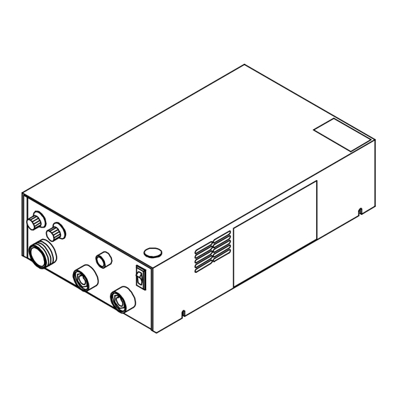
Page 24: Section 7 - Parts List
SECTION 7 – PARTS LIST Hardware is common and not available unless listed. ST-801 479-C Figure 7-1. Main Assembly OM-629 Page 20... - Page 25 Item Dia. Part Mkgs. Description Quantity Figure 7-1. Main Assembly ....199110 CIRCUIT CARD ASSY, control ....... . .
- Page 26 Item Dia. Part Mkgs. Description Quantity Figure 7-1. Main Assembly (Continued) ....180 181 ARC STARTER, pulsed HF ........
- Page 27 Call LIMITED WARRANTY – Subject to the terms and conditions APT, ZIPCUT & PLAZCUT Model Plasma Cutting below, Miller Electric Mfg. Co., Appleton, Wisconsin, warrants Torches 1-800-4-A-MILLER to its original retail purchaser that new Miller equipment sold...
- Page 28 FAX: 44 (0) 1204-598066 www.MillerWelds.com Contact the Delivering Carrier for: File a claim for loss or damage during shipment. For assistance in filing or settling claims, contact your distributor and/or equipment manufacturer’s Transportation Department. PRINTED IN USA 2000 Miller Electric Mfg. Co. 6/00...
Need help?
Do you have a question about the Snap Start II and is the answer not in the manual?
Questions and answers