
Related Manuals for Miller Electric Spectrum Plus


Summary of Contents for Miller Electric Spectrum Plus
- Page 1 OM-219 October 1995 Eff. w/Serial Number KE736265 Processes Air Plasma Cutting and Gouging Description Air Plasma Cutter Spectrum Plus Visit our website at www.MillerWelds.com...
- Page 2 Welding Process Manuals such as SMAW, GTAW, GMAW, and GMAW-P. Miller Electric manufactures a full line of welders and welding related equipment. For information on other quality Miller products, contact your local Miller distributor to receive the latest full line catalog or individual catalog sheets.
-
Page 3: Table Of Contents
TABLE OF CONTENTS SECTION 1 – SAFETY PRECAUTIONS - READ BEFORE USING ......1-1. Symbol Usage . -
Page 5: Section 1 - Safety Precautions - Read Before Using
SECTION 1 – SAFETY PRECAUTIONS - READ BEFORE USING pom _nd_5/97 1-1. Symbol Usage Means Warning! Watch Out! There are possible hazards with this procedure! The possible hazards are shown in the adjoining symbols. Y Marks a special safety message. This group of symbols means Warning! Watch Out! possible ELECTRIC SHOCK, MOVING PARTS, and HOT PARTS hazards. - Page 6 Work in a confined space only if it is well ventilated, or while wearing FLYING SPARKS can cause injury. an air-supplied respirator. Fumes from cutting and oxygen deple- tion can alter air quality causing injury or death. Be sure the Sparks and hot metal blow out from the cutting arc.
-
Page 7: Additional Symbols For Installation, Operation, And Maintenance
1-3. Additional Symbols For Installation, Operation, And Maintenance HOT PARTS can cause severe burns. FIRE OR EXPLOSION hazard. D Do not touch hot parts bare handed. D Do not locate unit on, over, or near combustible surfaces. D Allow cooling period before working on torch. D Do not install unit near flammables. -
Page 8: Emf Information
1-5. EMF Information Considerations About Welding Or Cutting And The Effects Of Low 1. Keep cables close together by twisting or taping them. Frequency Electric And Magnetic Fields 2. Arrange cables to one side and away from the operator. Welding or cutting current, as it flows through the welding or cutting cables, will cause electromagnetic fields. -
Page 9: Section 1 - Consignes De Sécurité - Lire Avant Utilisation
SECTION 1 – CONSIGNES DE SÉCURITÉ – LIRE AVANT UTILISATION pom_nd_fre_5/97 1-1. Signification des symboles Signifie Mise en garde ! Soyez vigilant ! Cette procédure présente des risques de danger ! Ceux-ci sont identifiés par des symboles adjacents aux directives. Y Identifie un message de sécurité... - Page 10 D N’approchez pas le tube du chalumeau et l’arc pilote lorsque la gâchette est D Ne mettez pas votre tête au–dessus des vapeurs. Ne respirez pas ces va- enfoncée. peurs. D Le câble de masse doit être pincé correctement sur la pièce à couper, métal D Si vous êtes à...
-
Page 11: Dangers Supplémentaires En Relation Avec L'installation, Le Fonctionnement Et La Maintenance
1-3. Dangers supplémentaires en relation avec l’installation, le fonctionnement et la maintenance DES PIECES CHAUDES peuvent pro- Risque D’INCENDIE OU voquer des brûlures graves. D’EXPLOSION. D Ne pas toucher des parties chaudes à mains nues. D Ne pas placer l’appareil sur, au-dessus ou à proximité D Laisser refroidir avant d’intervenir sur la torche. -
Page 12: Information Sur Les Champs Électromagnétiques
1-5. Information sur les champs électromagnétiques Données sur le soudage électrique et sur les effets, pour l’organisme, Garder les câbles ensembles en les torsadant ou en les des champs magnétiques basse fréquence attachant avec du ruban adhésif. Mettre tous les câbles du côté opposé de l’opérateur. Le courant de soudage ou de coupage passant dans les câbles de puis- sance crée des causera des champs électromagnétiques. -
Page 13: Section 2 - Installation
SECTION 2 – INSTALLATION 2-1. Specifications Maximum Rated Output Type Of Input (Varies With Type Of Open- Plasma Plasma Gas Range (Welding Power Output Of Output Circuit Flow/Pressure 110 Volts DC Source/Generator) Power Supply) Voltage DC Standard 25 ft 20 To 50 A @ (7.6 m) Torch 50% Duty Cycle Cable: 4 CFM... -
Page 14: Dimensions And Weight
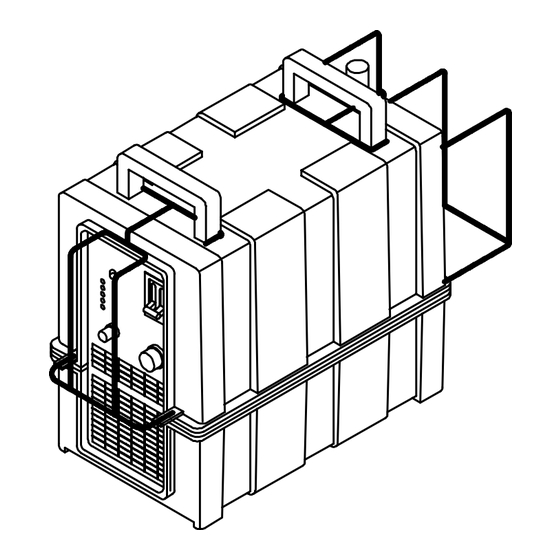
2-3. Dimensions And Weight Dimensions 17 in (432 mm) 10 in (254 mm) 19 in (483 mm) Weight Net: 68 lb (31 kg)* Ship: 87 lb (40.5 kg)* *Without Torch ST-800 868 2-4. Selecting A Location Lifting Handles Use lifting handles to lift unit. Hand Cart Movement And Airflow Use hand cart or similar device to... -
Page 15: Changing Current Range Setting At Dip Switch And Bus Bars
2-5. Changing Current Range Setting At DIP Switch And Bus Bars Current changeover dip switches and bus bars allow operation on two current range settings: High Range: 35 to 80 Amperes See rear cover for welding power source/generator cutting capacity. Current range is factory set for the high current range. -
Page 16: Input Terminal, Selecting Cable Sizes, And Weld Cable Preparation
2-6. Input Terminal, Selecting Cable Sizes, And Weld Cable Preparation NOTE If job requires cable larger than 3/0 AWG, use 2 ft (610 mm) or shorter piece of 3/0 AWG cable for Dinse-Type connector installation. Connect other end of short cable to the 4/0 or larger weld cable. -
Page 17: Connecting Air Compressor
2-7. Connecting Air Compressor Filter/Regulator Assembly Air Input Fitting (1/4 NPT Pipe Fitting) Hose (3/8 To 1/2 in) Air Compressor Obtain air compressor and hose. A quick connect fitting may also be installed onto air input fitting. Con- nect hose to air input fitting and route to air compressor. -
Page 18: Input Power Connections To Cutter
2-8. Input Power Connections To Cutter Cutter Negative (–) Input Terminal Compressor Welding Power Source Negative (–) Cable Connect one end of negative (–) cable to negative (–) output terminal of welding power source/generator. Connect remaining connector of negative (–) cable to negative (–) in- put terminal on cutter. -
Page 19: Section 3 - Operation
SECTION 3 – OPERATION 3-1. Controls Power/Circuit Breaker Switch Cutting Current Control Operation Mode Switch Pilot And Trouble Lights ST-800 873 3-2. Cutting Current Control Cutting Current Control Low Range Scale (18 to 50 Amperes) High Range Scale (30 to 80 Amperes) Control scales are in amperes. -
Page 20: Operation Mode Switch
3-3. Operation Mode Switch Operation Mode Switch Use switch to safely adjust gas/air pressure without activating cutting output. Torch Mode (Standard) Use these mode positions for stan- dard cutter units. POWER Air Assist Mode (Optional) Use these mode positions for cut- ters equipped with optional air am- Set Switches plifier kit. -
Page 21: Power/Circuit Breaker Switch And Pilot Light
3-4. Power/Circuit Breaker Switch And Pilot Light Power/Circuit Breaker Switch Pilot Light Use Power/Circuit Breaker switch to turn unit and pilot light On and Off. Power/Circuit Breaker switch CB1 also protects the unit from overload. If CB1 trips, the unit shuts down. If CB1 trips, reduce welding power source/generator cutting amper- age by 10 amperes. -
Page 22: Section 4 - Maintenance & Troubleshooting
SECTION 4 – MAINTENANCE & TROUBLESHOOTING 4-1. Routine Maintenance Y Disconnect power before maintaining. Each Use Check For Air Bleeding From Check Torch Extractor/Dryer Assembly Tip, Electrode, Check Gas/Air (See Section 4-5) And Shield Cup Pressure Every Week Drain Moisture From Check Trigger Filter/Regulator Assembly Disabled System... -
Page 23: Removing Case And Discharging Input And Output Capacitors
4-2. Removing Case And Discharging Input And Output Capacitors Y Significant DC voltage can remain on capacitors after unit is Off. Always discharge capacitors as shown to be sure they have discharged before working on unit. Turn Off welding power source and Bleeder Resistor cutter, and disconnect input power Specifications... -
Page 24: Overload Protection
NOTE If cutting arc is not started within 5 seconds of pilot arc, wait 20 seconds for circuit to reset before trying to restart pilot arc. 4-3. Overload Protection Y Turn Off welding power source cutter, disconnect input power. Stop engine on welding generator. -
Page 25: Trouble Lights
4-4. Trouble Lights Trigger Light Lights when torch trigger is pressed. Transfer Light Lights when the transfer from pilot to plasma arc occurs. Stays lit as long as plasma arc is present. If certain problems occur, the Transfer light goes off, one of the TRIGGER following trouble lights comes on, and output stops. -
Page 26: Filter/Regulator Assembly And Extractor/Dryer Assembly
4-5. Filter/Regulator Assembly And Extractor/Dryer Assembly Y Turn Off welding power source cutter, disconnect input power. Stop engine on welding generator. Filter/ Regulator Assembly Drain Plug To drain moisture from filter/regula- tor assembly, rotate drain plug counterclockwise. Close drain plug after moisture is completely drained from filter/regulator assembly. -
Page 27: Torch Hose And Lead Connections
4-6. Torch Hose And Lead Connections If torch or work cable needs to be removed or replaced, proceed as follows: Y Turn Off welding power source cutter, disconnect input power. Stop engine on welding generator. Remove top of case according to Section 4-2. -
Page 28: Checking Trigger Disabled System
4-7. Checking Trigger Disabled System Torch Cup Turn Power On, loosen cup, and press trigger for one second. If trig- ger disabling system works proper- ly, the Trigger light does not come on. Tighten cup and turn Off power. If Trigger light does comes on, sys- tem is not working properly. - Page 29 Trouble Remedy Gas/air flows in Gas Set position, but Check torch connections (see torch Owner’s Manual). does not flow when trigger is pressed. No gas/air flow; Pilot light on; trouble Check torch connections (see torch Owner’s Manual). lights off; fan motor FM running. Check for proper installation of torch parts and consumables (see torch Owner’s Manual).
-
Page 30: Section 5 - Electrical Diagrams
SECTION 5 – ELECTRICAL DIAGRAMS SC-171 596-A Figure 5 -1. Circuit Diagram For Cutter OM-222 Page 26... -
Page 31: Section 6 - Hf In Plasma Cutting
SECTION 6 – HF IN PLASMA CUTTING 6-1. High Frequency In Plasma Arc Cutting (PAC) É É É É É É É É É Plasma Arc Torch É É É É É É É É É High-Frequency Voltage É É É É É É É É É É... -
Page 32: Correct Installation
6-3. Correct Installation A. Worksite Requirements Cutting Zone 50 ft (15 m) 50 ft (15 m) Ground All Metal Objects And All Wiring In Cutting Zone Using #12 AWG Ground Wire Workpiece If Required By Codes Nonmetal Building Metal Building Ref. - Page 33 Notes OM-219 Page 29...
-
Page 34: Section 7 - Parts List
SECTION 7 – PARTS LIST Fig 7-2 44 45 46 47 Figure 7-1. Main Assembly OM-219 Page 30... - Page 35 ST-800 867-A OM-219 Page 31...
- Page 36 Item Dia. Part Mkgs. Description Quantity Figure 7-1. Main Assembly ... . +171 320 KIT, replace case top ..........
- Page 37 Item Dia. Part Mkgs. Description Quantity Figure 7-1. Main Assembly ..171 327 CIRCUIT BREAKER, DC ..........
- Page 38 ST-800 885–A Figure 7-2. Center Baffle OM-219 Page 34...
- Page 39 Item Dia. Part Mkgs. Description Quantity Figure 7-2. Center Baffle (Figure 7-1 Item 5) ..171 272 CONTROL BOARD, (consisting of) ........
- Page 40 ST-800 889 Figure 7-3. Arc Starter Assembly OM-219 Page 36...
- Page 41 Item Dia. Part Mkgs. Description Quantity 171 157 Figure 7-3. Arc Starter Assembly ..171 491 MAIN INDUCTOR, (consisting of) ........
- Page 42 WELDING POWER SOURCE/GENERATOR CUTTING CAPACITY MANUFACTURER: MILLER ELECTRIC MANUFACTURER: LINCOLN ELECTRIC CO. Material Thickness Material Thickness Welding Power Source Model Welding Power Source Model 1/2 in 3/4 in 7/8 in 1/2 in 3/4 in 7/8 in DELTAWELD 451 or 452...
- Page 43 Call LIMITED WARRANTY – Subject to the terms and conditions APT, ZIPCUT & PLAZCUT Model Plasma Cutting below, Miller Electric Mfg. Co., Appleton, Wisconsin, warrants Torches 1-800-4-A-MILLER to its original retail purchaser that new Miller equipment sold...
- Page 44 FAX: 44 (0) 1204-598066 www.MillerWelds.com Contact the Delivering Carrier for: File a claim for loss or damage during shipment. For assistance in filing or settling claims, contact your distributor and/or equipment manufacturer’s Transportation Department. PRINTED IN USA 2000 Miller Electric Mfg. Co. 6/00...
Need help?
Do you have a question about the Spectrum Plus and is the answer not in the manual?
Questions and answers