Miller Millermatic 300 Owner's Manual
Arc welding power source and wire feeder
Hide thumbs
Also See for Millermatic 300:
- Owner's manual (44 pages) ,
- Owner's manual (48 pages) ,
- Owner's manual (52 pages)

Related Manuals for Miller Millermatic 300


Summary of Contents for Miller Millermatic 300
- Page 1 OM-1317 185 529M November 1999 Processes MIG (GMAW) Welding Flux Cored (FCAW) Welding Description Arc Welding Power Source and Wire Feeder Millermatic 300 Visit our website at www.MillerWelds.com...
- Page 2 Welding Process Manuals such as SMAW, GTAW, GMAW, and GMAW-P. Miller Electric manufactures a full line of welders and welding related equipment. For information on other quality Miller products, contact your local Miller distributor to receive the latest full line catalog or individual catalog sheets.
-
Page 3: Table Of Contents
TABLE OF CONTENTS SECTION 1 – SAFETY PRECAUTIONS - READ BEFORE USING ......1-1. -
Page 5: Section 1 - Safety Precautions - Read Before Using
SECTION 1 – SAFETY PRECAUTIONS - READ BEFORE USING som _nd_4/98 1-1. Symbol Usage Means Warning! Watch Out! There are possible hazards with this procedure! The possible hazards are shown in the adjoining symbols. This group of symbols means Warning! Watch Out! possible Y Marks a special safety message. - Page 6 ARC RAYS can burn eyes and skin. BUILDUP OF GAS can injure or kill. D Shut off shielding gas supply when not in use. Arc rays from the welding process produce intense D Always ventilate confined spaces or use visible and invisible (ultraviolet and infrared) rays that can burn eyes and skin.
-
Page 7: Additional Symbols For Installation, Operation, And Maintenance
1-3. Additional Symbols For Installation, Operation, And Maintenance FIRE OR EXPLOSION hazard. MOVING PARTS can cause injury. D Do not install or place unit on, over, or near D Keep away from moving parts such as fans. combustible surfaces. D Keep all doors, panels, covers, and guards D Do not install unit near flammables. -
Page 8: Emf Information
1-5. EMF Information Considerations About Welding And The Effects Of Low Frequency 1. Keep cables close together by twisting or taping them. Electric And Magnetic Fields 2. Arrange cables to one side and away from the operator. Welding current, as it flows through welding cables, will cause electro- magnetic fields. -
Page 9: Section 1 - Consignes De Securite - Lire Avant Utilisation
SECTION 1 – CONSIGNES DE SECURITE – LIRE AVANT UTILISATION som _nd_fre 4/98 1-1. Signification des symboles Signifie Mise en garde ! Soyez vigilant ! Cette procédure présente des risques de danger ! Ceux-ci sont identifiés par des symboles adjacents aux directives. Ce groupe de symboles signifie Mise en garde ! Soyez vigilant ! Il y a des Y Identifie un message de sécurité... - Page 10 LES RAYONS DE L’ARC peuvent pro- LES ACCUMULATIONS DE GAZ ris- voquer des brûlures dans les yeux et quent de provoquer des blessures ou sur la peau. même la mort. Le rayonnement de l’arc du procédé de soudage D Fermer l’alimentation du gaz protecteur en cas de génère des rayons visibles et invisibles intenses non utilisation.
-
Page 11: Dangers Supplémentaires En Relation Avec L'installation, Le Fonctionnement Et La Maintenance
1-3. Dangers supplémentaires en relation avec l’installation, le fonctionnement et la maintenance Risque D’INCENDIE OU DES ORGANES MOBILES peuvent D’EXPLOSION. provoquer des blessures. D Ne pas placer l’appareil sur, au-dessus ou à proxi- D Rester à l’écart des organes mobiles comme le mité... -
Page 12: Principales Normes De Sécurité
1-4. Principales normes de sécurité Safety in Welding and Cutting, norme ANSI Z49.1, de l’American Wel- Safe Handling of Compressed Gases in Cylinders, CGA Pamphlet P-1, ding Society, 550 N.W. Lejeune Rd, Miami FL 33126 de la Compressed Gas Association, 1235 Jefferson Davis Highway, Suite 501, Arlington, VA 22202. -
Page 13: Section 2 - Installation
SECTION 2 – INSTALLATION 2-1. Specifications Amps Input at Rated Output, 50 or 60 Hz; Three-Phase Max. Open Max. Open Rated Output Circuit Voltage 200 V 230 V 460 V 300 A at 32 VDC, 240 A at 32 VDC, 23.5 18.6 60% Duty Cycle... -
Page 14: Volt-Ampere Curve
2-3. Volt-Ampere Curve Normal Volt-Ampere Curves The volt-ampere curves show the normal minimum and maximum voltage and amperage output capa- bilities of the welding power source. Curves of other settings fall be- tween the curves shown. Overload Volt-Ampere Curves When unit is used beyond capacity, circuitry senses the overload and shuts down unit output. -
Page 15: Installing Welding Gun (Welding Gun Not Included)
2-5. Installing Welding Gun (Welding Gun Not Included) Drive Assembly Gun Securing Knob Gun End Loosen securing knob. Insert gun end through opening until it bottoms against drive assembly. Tighten knob. Gun Trigger Plug Insert plug into receptacle, and tighten threaded collar. Close door. -
Page 16: Remote 14 Receptacle
2-7. Remote 14 Receptacle Socket* Socket Information 24 volts ac. Protected by circuit breaker CB2. Contact closure to A completes 24 volts ac contactor control circuit. C L N Circuit common for 24 volts ac circuit. Ref. ST-152 973-A *The remaining sockets are not used. 2-8. -
Page 17: Installing Wire Spool And Adjusting Hub Tension
2-9. Installing Wire Spool and Adjusting Hub Tension Use compression spring with 8 in (200 mm) spools. When a slight force is needed to turn spool, tension is set. Tools Needed: 15/16 in ST-072573-B OM-1317 Page 13... -
Page 18: Inductance Selection
2-10. Inductance Selection Remove left side panel. Stabilizer Z Tapped stabilizer Z is factory con- nected to the stabilizer tap which suits most GMAW applications. Tools Needed: Stabilizer Z controls the inductance applied to the weld current. To in- crease inductance and wet out the 3/8, 7/16 in weld puddle, connect to stabilizer Z ending. -
Page 19: Selecting A Location And Connecting Input Power
2-12. Selecting a Location and Connecting Input Power Tools Needed: 3/8 in 3/8 in GND/PE 18 in (457 mm) for airflow GND/PE Connect First Size and ratings must comply with applicable codes (see Section 2-11). Install conductors in conduit or equivalent into a deenergized line disconnect device. -
Page 20: Threading Welding Wire
2-13. Threading Welding Wire Wire Spool Welding Wire Inlet Wire Guide Pressure Adjustment Knob Drive Roll Outlet Wire Guide Gun Conduit Cable Lay gun cable out straight. Tools Needed: Hold wire tightly to keep it from unraveling. 6 in (150 mm) Open pressure assembly. -
Page 21: Section 3 - Operation
SECTION 3 – OPERATION 3-1. Controls Voltage Control The scale around control is actual voltage. Wire Speed Control The scale around control is actual wire feed speed. Power Switch Pilot Light ST-186 764 OM-1317 Page 17... -
Page 22: Section 4 - Maintenance &Troubleshooting
SECTION 4 – MAINTENANCE &TROUBLESHOOTING 4-1. Routine Maintenance Maintain more often Y Disconnect power during severe conditions. before maintaining. 3 Months Replace unreadable labels Repair or replace cracked weld cable Clean and tighten weld terminals 6 Months Remove drive roll and Blow out or vacuum inside. -
Page 23: Changing Drive Roll And Wire Inlet Guide
4-4. Changing Drive Roll and Wire Inlet Guide Securing Screw Inlet Wire Guide Loosen screw. Slide tip as close to drive rolls as possible without touching. Tighten screw. Anti-Wear Guide Install guide as shown. Drive Roll Install correct drive roll for wire size and type. -
Page 24: Troubleshooting
4-6. Troubleshooting Trouble Remedy No weld output; wire does not feed. Be sure line disconnect switch is On (see Section 2-12). Replace building line fuse or reset circuit breaker if open (see Section 2-12). Reset circuit breaker CB1 (see Section 4-2). Secure gun trigger connections (see Section 2-5). -
Page 25: Section 5 - Electrical Diagram
SECTION 5 – ELECTRICAL DIAGRAM SC-185 561-C Figure 5-1. Circuit Diagram OM-1317 Page 21... -
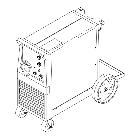
Page 26: Section 6 - Parts List
SECTION 6 – PARTS LIST Hardware is common and not available unless listed. Ref. ST-801 951-A Figure 6-1. Main Assembly OM–1317 Page 22... - Page 27 Item Dia. Part Mkgs. Description Quantity Figure 6-1. Main Assembly . . . PLG8 008 072 . . . HOUSING RECEPTACLE & SOCKETS ....... .
- Page 28 Hardware is common and not available unless listed. Ref. ST-801 952-A Figure 6-2. Baffle, Center w/Components OM–1317 Page 24...
- Page 29 Item Dia. Part Mkgs. Description Quantity Figure 6-2. Baffle, Center w/Components (Fig 6-1 Item 2) ....058 427 . . . RING, retaining spool ..........
- Page 30 Item Dia. Part Mkgs. Description Quantity Figure 6-3. Panel, Front w/Components (Fig 6-1 Item ....+188 711 PANEL, front control ..........
- Page 31 Item Dia. Part Mkgs. Description Quantity Figure 6-4. Wire Drive And Gears (Fig 6-2 Item 27) ....602 009 . . . SCREW, .250-20 x 1.25 soc hd gr 8 .
- Page 32 Table 6-1. Drive Roll And Wire Guide Kits Note Base selection of drive rolls upon the following recommended usages: V-Grooved rolls for hard wire. U-Grooved rolls for soft and soft shelled cored wires. U-Cogged rolls for extremely soft shelled wires (usually hard surfacing types). V-Knurled rolls for hard shelled cored wires.
- Page 33 Notes...
- Page 34 Notes...
- Page 35 Call LIMITED WARRANTY – Subject to the terms and conditions APT, ZIPCUT & PLAZCUT Model Plasma Cutting below, Miller Electric Mfg. Co., Appleton, Wisconsin, warrants Torches 1-800-4-A-MILLER to its original retail purchaser that new Miller equipment sold...
-
Page 36: Options And Accessories
FAX: 44 (0) 1204-598066 www.MillerWelds.com Contact the Delivering Carrier for: File a claim for loss or damage during shipment. For assistance in filing or settling claims, contact your distributor and/or equipment manufacturer’s Transportation Department. PRINTED IN USA 2000 Miller Electric Mfg. Co. 6/00...