Table of Contents
Advertisement
Quick Links
Advertisement
Table of Contents

Related Manuals for Miller Axcess 300 CE


Summary of Contents for Miller Axcess 300 CE
- Page 1 OM-230 032S 2013−05 Processes MIG (GMAW) Welding Pulsed MIG (GMAW-P) Flux Cored (FCAW) Welding Automatic Welding Description Automatic Welding Interface And Arc Welding Power Source Axcess 300 Visit our website at File: Advanced Manufacturing Systems www.MillerWelds.com/ams...
- Page 2 We know you don’t have time to do it any other way. That’s why when Niels Miller first started building arc welders in 1929, he made sure his products offered long-lasting value and superior quality.
-
Page 3: Table Of Contents
TABLE OF CONTENTS SECTION 1 − SAFETY PRECAUTIONS - READ BEFORE USING ....... . . 1-1. - Page 4 TABLE OF CONTENTS SECTION 9 − SAFETY PRECAUTIONS FOR SERVICING ........9-1.
- Page 5 DECLARATION OF CONFORMITY for European Community (CE marked) products. MILLER Electric Mfg. Co., 1635 Spencer Street, Appleton, WI 54914 U.S.A. declares that the product(s) identified in this declaration conform to the essential requirements and provisions of the stated Council Directive(s) and Standard(s).
-
Page 7: Section 1 − Safety Precautions - Read Before Using
SECTION 1 − SAFETY PRECAUTIONS - READ BEFORE USING som 2011−10 Protect yourself and others from injury — read, follow, and save these important safety precautions and operating instructions. 1-1. Symbol Usage DANGER! − Indicates a hazardous situation which, if Indicates special instructions. - Page 8 D Remove stick electrode from holder or cut off welding wire at FUMES AND GASES can be hazardous. contact tip when not in use. D Wear oil-free protective garments such as leather gloves, heavy Welding produces fumes and gases. Breathing shirt, cuffless trousers, high shoes, and a cap.
-
Page 9: Additional Symbols For Installation, Operation, And Maintenance
1-3. Additional Symbols For Installation, Operation, And Maintenance FIRE OR EXPLOSION hazard. BATTERY EXPLOSION can injure. D Do not install or place unit on, over, or near D Do not use welder to charge batteries or jump combustible surfaces. start vehicles unless it has a battery charging feature designed for this purpose. -
Page 10: California Proposition 65 Warnings
1-4. California Proposition 65 Warnings Welding or cutting equipment produces fumes or gases This product contains chemicals, including lead, known to which contain chemicals known to the State of California to the state of California to cause cancer, birth defects, or other cause birth defects and, in some cases, cancer. -
Page 11: Section 2 − Consignes De Sécurité − Lire Avant Utilisation
SECTION 2 − CONSIGNES DE SÉCURITÉ − LIRE AVANT UTILISATION fre_som_2011−10 Pour écarter les risques de blessure pour vous−même et pour autrui — lire, appliquer et ranger en lieu sûr ces consignes relatives aux précautions de sécurité et au mode opératoire. 2-1. - Page 12 Il reste une TENSION DC NON NÉGLIGEABLE dans LE SOUDAGE peut provoquer un les sources de soudage onduleur UNE FOIS incendie ou une explosion. l’alimentation coupée. Le soudage effectué sur des conteneurs fermés tels D Arrêter les convertisseurs, débrancher le courant électrique et que des réservoirs, tambours ou des conduites peut décharger les condensateurs d’alimentation selon les instructions provoquer leur éclatement.
-
Page 13: Dangers Supplémentaires En Relation Avec L'installation, Le Fonctionnement Et La Maintenance
ACCUMULATIONS LES BOUTEILLES peuvent exploser risquent de provoquer des blessures si elles sont endommagées. ou même la mort. Les bouteilles de gaz comprimé contiennent du gaz sous haute pression. Si une bouteille est D Fermer l’alimentation du gaz comprimé en cas endommagée, elle peut exploser. -
Page 14: Proposition Californienne 65 Avertissements
Les PIÈCES MOBILES peuvent RAYONNEMENT HAUTE causer des blessures. FRÉQUENCE (H.F.) risque provoquer des interférences. D Ne pas s’approcher des organes mobiles. D Ne pas s’approcher des points de coincement D Le rayonnement haute fréquence (H.F.) peut tels que des rouleaux de commande. provoquer des interférences avec les équi- pements de radio−navigation et de com- LES FILS DE SOUDAGE peuvent... -
Page 15: Principales Normes De Sécurité
2-5. Principales normes de sécurité Safety in Welding, Cutting, and Allied Processes, ANSI Standard Z49.1, Spectrum Way, Suite 100, Ontario, Canada L4W 5NS (phone: is available as a free download from the American Welding Society at 800-463-6727, website: www.csa-international.org). http://www.aws.org or purchased from Global Engineering Documents Safe Practice For Occupational And Educational Eye And Face Protec- (phone: 1-877-413-5184, website: www.global.ihs.com). - Page 16 OM-230 032 Page 10...
-
Page 17: Section 3 − Definitions
SECTION 3 − DEFINITIONS 3-1. Additional Safety Symbols and Definitions Some symbols are found only on CE products. Warning! Watch Out! There are possible hazards as shown by the symbols. Safe1 2012−05 Wear dry insulating gloves. Do not touch electrode with bare hand. Do not wear wet or damaged gloves. Safe2 2012−05 Protect yourself from electric shock by insulating yourself from work and ground. - Page 18 Do not remove or paint over (cover) the label. Safe20 2012−05 When power is applied failed parts can explode or cause other parts to explode. Safe26 2012−05 Flying pieces of parts can cause injury. Always wear a face shield when servicing unit. Safe27 2012−05 Always wear long sleeves and button your collar when servicing unit.
-
Page 19: Miscellaneous Symbols And Definitions
3-2. Miscellaneous Symbols And Definitions Some symbols are found only on CE products. Direct Current Alternating Amperage Voltage (DC) Current (AC) Output Circuit Breaker Remote Positive Negative Voltage Input Protective Earth Arc Force Constant Voltage Inductance (Ground) Three Phase Static Frequency Con- Gas Metal Arc Increase... -
Page 20: Section 4 − Specifications
SECTION 4 − SPECIFICATIONS 4-1. Serial Number And Rating Label Location The serial number and rating information for this product is located on the rear. Use rating label to determine input power requirements and/or rated output. For future reference, write serial number in space provided on back cover of this manual. 4-2. -
Page 21: Duty Cycle And Overheating
4-4. Duty Cycle And Overheating Duty Cycle is percentage of 10 minutes that unit can weld at rated load without overheating. If unit overheats, thermostat(s) opens, output stops, and cooling fan runs. Wait fifteen minutes for unit to cool. Reduce amperage or 3 PHASE duty cycle before welding. -
Page 22: Environmental Specifications
4-6. Environmental Specifications A. IP Rating IP Rating IP21S This equipment is designed for indoor use and is not intended to be used or stored outside. B. Information On Electromagnetic Fields (EMF) This equipment shall not be used by the general public as the EMF limits for the general public might be exceeded during welding. This equipment is built in accordance with EN 60974−1 and is intended to be used only in an occupational environment (where the general public access is prohibited or regulated in such a way as to be similar to occupational use) by an expert or an instructed person. -
Page 23: Section 5 − Installation
SECTION 5 − INSTALLATION Appearance of actual unit may vary from unit shown in manual. 5-1. Selecting A Location Do not move or operate Movement Tipping unit where it could tip. Location Do not stack units. Beware of Special installation may be required where gasoline or volatile tipping. -
Page 24: Rear Panel Receptacles And Supplementary Protectors
5-3. Rear Panel Receptacles And Supplementary Protectors 115 V 10 A AC Receptacle RC2 Receptacle supplies single-phase power. Maximum output from RC2 is limited by supplementary protector CB1 to 10 amps. Supplementary Protector CB1 Supplementary Protector CB2 CB1 protects 115 volt receptacle RC2 from overload. -
Page 25: Electrical Service Guide
5-5. Electrical Service Guide Elec Serv 2011−08 Failure to follow these electrical service guide recommendations could create an electric shock or fire hazard. These recommendations are for a dedicated circuit sized for the rated output and duty cycle of the welding power source. In dedicated circuit installations, the National Electrical Code (NEC) allows the receptacle or conductor rating to be less than the rating of the circuit protection device. -
Page 26: Connecting 3−Phase Input Power
5-6. Connecting 3−Phase Input Power = GND/PE Earth Ground Route input conductors to filter board. Route ground conductor through tubing and current transducer to ground terminal. Tools Needed: 5/16 in. Input5 2012−05 Ref. 803 766-C / 804 650-A / Ref. 803 855-A / 219 842-B OM-230 032 Page 20... - Page 27 5-6. Connecting 3−Phase Input Power (Continued) Turn Off welding power source, and Section 5-5. Conductors must comply with Connect input conductors L1, L2, and L3 to check voltage on input capacitors national, state, and local electrical codes. If welding power source line terminals. according to Section 10-1 before applicable, use lugs of proper amperage Reinstall side panel onto welding power...
-
Page 28: Section 6 − Recommended Setup Procedures
SECTION 6 − RECOMMENDED SETUP PROCEDURES 6-1. Weld Output Terminals And Selecting Cable Sizes* NOTICE − The Total Cable Length in Weld Circuit (see table below) is the combined length of both weld cables. For example, if the power source is 30 m (100 ft) from the workpiece, the total cable length in the weld circuit is 60 m (2 cables x 30 m). -
Page 29: Connecting To Weld Terminals
6-2. Connecting To Weld Terminals If using an electrode negative (straight polarity) process, the volt sense lead must be disconnected from the work. Do not place anything between weld cable terminal and copper bar. Correct Installation Incorrect Installation Tools Needed: 19 mm (3/4 in.) Ref. -
Page 30: Welding Circuit
6-3. Welding Circuit Minimizing the welding circuit loop can prevent extreme voltage drops that produce poor welding characteristics. Welding Power Source Electrode Cable Feeder Cable Work Cable Voltage Sensing Lead Wire Feeder Standard Welding Circuit Workpiece In pulse welding applications using inverter power sources,... -
Page 31: Arranging Welding Cables To Reduce Welding Circuit Inductance
6-4. Arranging Welding Cables To Reduce Welding Circuit Inductance Welding Power Source Electrode Cable Feeder Cable Work Cable Voltage Sensing Lead Wire Feeder Workpiece The method used to arrange cables has significant affect welding properties. As an example, Accupulse and RMD welding processes can produce high welding circuit inductance depending on cable... -
Page 32: Using Multiple Welding Power Sources
Welding on a single workpiece using multiple welding power sources can cause arc blow and arc impedance to develop or intensify. 6-5. Using Multiple Welding Power Sources Welding Power Source Electrode Cable Feeder Cable Work Cable Voltage Sensing Lead Wire Feeder Workpiece Each welding power source should have a separate work cable connection... -
Page 33: Voltage Sensing Lead And Work Cable Connections For Multiple Welding Arcs
6-6. Voltage Sensing Lead And Work Cable Connections For Multiple Welding Arcs A. Bad Setup Current Flow Path Ref. 804 528-A Welding Power Source Workpiece across the workpiece will not be measured correctly for the voltage feedback signal. Electrode Cable This arrangement is a bad setup due to Voltage feedback to the welding power Feeder Cable... - Page 34 B. Better Setup Current Flow Path Ref. 804 529-A Welding Power Source Wire Feeder the welding power sources. The most accurate voltage sensing may not be Electrode Cable Workpiece achieved due to voltage drops in the Feeder Cable workpiece. This require Work Cable This arrangement is a better setup for...
- Page 35 C. Best Setup Current Flow Path Ref. 804 530-A Welding Power Source Voltage Sensing Lead This arrangement is the best setup for proper voltage sensing at the workpiece. Electrode Cable Wire Feeder Voltage feedback to the welding power Feeder Cable sources will more accurate and result in Work Cable Workpiece...
-
Page 36: Section 7 − Operation
SECTION 7 − OPERATION 7-1. Front Panel Switches Ref. 803 669-A Power Switch Pilot Light PDA Port Light indicates status of welding power Turns unit On or Off. PC Port source, on when unit is on and off when unit is off. -
Page 37: Section 8 − Maintenance
SECTION 8 − MAINTENANCE 8-1. Routine Maintenance Maintain more often Disconnect power before maintaining. during severe conditions. n = Check Z = Change ~ = Clean l = Replace Reference * To be done by Factory Authorized Service Agent Every l Unreadable Labels ~ Weld Terminals l Damaged Gas Hose... - Page 38 SECTION 9 − SAFETY PRECAUTIONS FOR SERVICING Protect yourself and others from injury — read, follow, and save these important safety precautions and operating instructions. 9-1. Symbol Usage OM-230 032S - 2013−05, safety_stm 2011−10 DANGER! − Indicates a hazardous situation which, if Indicates special instructions.
- Page 39 MOVING PARTS can injure. H.F. RADIATION can cause interference. D Keep away from moving parts such as fans. D High-frequency (H.F.) can interfere with radio navigation, safety services, computers, and D Keep away from pinch points such as drive communications equipment. rolls.
- Page 40 SECTION 10 − TROUBLESHOOTING 10-1. Removing Cover and Measuring Input Capacitor Voltage Turn Off welding power source, and disconnect in- put power. Significant DC voltage can Tools Needed: remain on capacitors after unit is Off. Always check the 5/16 in. voltage as shown to be sure the input capacitors have discharged before working...
- Page 41 10-2. Weld Process Board PC4 Diagnostic LEDs Weld Process Board PC4 Diagnostic LEDs are visible inside unit, located on PC4 mounted on the top tray. Refer to Section 10-3 for information on diagnostic LEDs. Reinstall cover after checking diagnostic LEDs. LED1 LED2 LED3...
- Page 42 10-4. Network And Module Status LEDs Network Status LEDs The following is a network status LED: LED4 on the PCM circuit board. Status Diagnosis The circuit board is not on-line with the network or there is no power applied to the circuit board. Green The circuit board is operating normally and the on-line connection is made with the network.
- Page 43 10-5. Troubleshooting Trouble Remedy No weld output; completely inoperative Place line disconnect in On position (see Section 5-6). Check and replace line fuse(s), if necessary, or reset circuit breaker (see Section 5-6). Check for proper input power connections (see Section 5-6). No weld output;...
- Page 44 SECTION 11 − ELECTRICAL DIAGRAMS Figure 11-1. Circuit Diagram For Welding Power Source OM-230 032 Page 38...
- Page 45 263 485-A OM-230 032 Page 39...
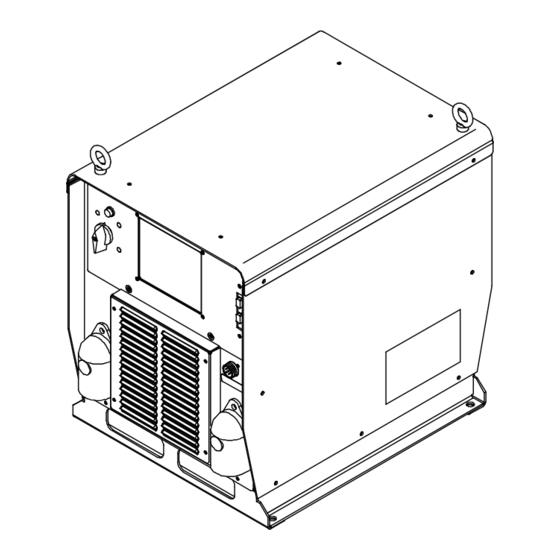
- Page 46 SECTION 12 − PARTS LIST Hardware is common and not available unless listed. 4 − Fig 12-3 6 − Fig 12-4 5 − Fig 12-2 17 − Fig 12-5 Ref. 804 651-D Figure 12-1. Main Assembly OM-230 032 Page 40...
- Page 47 Item Dia. Part Mkgs. Description Quantity Figure 12-1. Main Assembly ....210492 . . . Cover, Top ........... .
- Page 48 Hardware is common and not available unless listed. 20 21 802 955-C Figure 12-2. Windtunnel Assembly LH And RH Item Dia. Part Mkgs. Description Quantity Figure 12-2. Windtunnel Assembly LH And RH (Fig 12-1 Item 6) ....214597 .
- Page 49 Item Dia. Part Mkgs. Description Quantity Figure 12-2. Windtunnel Assembly LH And RH (Continued) (Fig 12-1 Item 6) ....201695 ..Clamp, Capacitor (Bottom) .
- Page 50 Hardware is common and not available unless listed. 803 422-B Figure 12-3. Top Tray Assembly Item Dia. Part Mkgs. Description Quantity Figure 12-3. Top Tray Assembly (Fig 12-1 Item 4) ... . . 239598 .
- Page 51 Hardware is common and not available unless listed. 803 672-B Figure 12-4. Rear Panel Assembly Item Dia. Part Mkgs. Description Quantity Figure 12-4. Rear Panel Assembly (Fig 12-1 Item 8) ....210478 .
- Page 52 Hardware is common and not available unless listed. Ref. 804 676-A Figure 12-5. Front Panel Assembly Item Dia. Part Mkgs. Description Quantity Figure 12-5. Front Panel Assembly (Fig 12-1 Item 14) ....207456 .
- Page 53 Item Dia. Part Mkgs. Description Quantity Figure 12-5. Front Panel Assembly (Continued) ....207979 . . . Box, Louver ...........
- Page 54 Notes...
- Page 55 Effective January 1, 2013 (Equipment with a serial number preface of MD or newer) This limited warranty supersedes all previous Miller warranties and is exclusive with no other guarantees or warranties expressed or implied. Warranty Questions? LIMITED WARRANTY − Subject to the terms and conditions below, 6 Months —...
- Page 56 Contact the Delivering Carrier to: File a claim for loss or damage during shipment. For assistance in filing or settling claims, contact your distributor and/or equipment manufacturer’s Transportation Department. ORIGINAL INSTRUCTIONS − PRINTED IN USA 2013 Miller Electric Mfg. Co. 2013−01...
Need help?
Do you have a question about the Axcess 300 CE and is the answer not in the manual?
Questions and answers