Advertisement
OPERATING MANUAL
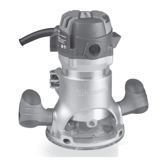
11 A 2.0 HP Plunge/Fixed Router
241-0836
Parts missing or damaged? Questions?
Toll-Free Help Line – 1-866-917-4374
IMPORTANT :
Read this operating manual carefully before using your new tool. Pay
close attention to all Safety Instructions, Warnings, and Caution sections.
Use your tool properly and only for its intended use
Safety symbols in this manual are used to indicate possible dangers. The
safety symbols and their explanations require your full understanding. The
safety warnings do not eliminate any danger by themselves, and they are not
a substitute for proper accident prevention measures.
This Safety Alert Symbol indicates caution, warning, or danger. Failure
to obey a safety warning may result in serious injury to yourself or to others.
To reduce the risk of injury, fire, or electric shock, always follow the safety
precautions.
1
Advertisement

Subscribe to Our Youtube Channel
Summary of Contents for MasterForce 241-0836
- Page 1 OPERATING MANUAL 11 A 2.0 HP Plunge/Fixed Router 241-0836 Parts missing or damaged? Questions? Toll-Free Help Line – 1-866-917-4374 IMPORTANT : Read this operating manual carefully before using your new tool. Pay close attention to all Safety Instructions, Warnings, and Caution sections.
-
Page 2: Table Of Contents
TABLE OF CONTENTS RULES FOR SAFE OPERATION KNOW YOUR TOOL Specification……………..…………………………..………..…..……Page 2 Before operating this tool, carefully read this operating manual and all of the labels affixed to the router. Keep this manual available for future reference. Rules for Safe Operation…………………………………………….…Page 3 Operation..………..………..………..………..………..………..………Page 8 IMPORTANT Accessories..………..………..………..………..………..………...…... - Page 3 Water entering a power tool will increase the risk of electric shock. the tool. A power source with voltage greater than that specified for the tool can result in serious injury to the user – as well as damage to the tool. Do not abuse the cord.
- Page 4 SPECIFIC SAFETY INSTRUCTIONS FOR THE PLUNGE ROUTER WARNING: Use of this tool can generate and/or disperse dust, which may cause serious and permanent respiratory or other injuries. Always use the ap- WARNING: Read all instructions. Failure to comply with all of the follow- propriate certified respiratory device to protect against dust exposure.
-
Page 5: Operation
OPERATION 9. Variable speed dial. Six variable speeds allow the operator to control and adjust to speed and power specifications. The speed and power of the KNOW YOUR ROUTER (see Fig. 1) router can be increased or decreased by rotating the dial. Before attempting to use this router, familiarize yourself with all of its 10. - Page 6 SWITCHING FROM THE PLUNGE SETTING THE CUTTING DEPTH FOR Fig. 4 Fig. 7 Plunge Base FIXED BASE ROUTING (see Fig. 7) BASE TO THE FIXED BASE (see Fig. 2. to Fig. 5) The bit depth can be adjusted by turning the depth adjustment knob To remove the plunge base clockwise or counter-clockwise.
- Page 7 OPERATING THE ROUTER overload the motor. Use two or more passes for extra-large cuts, especially in the case of hardwood. • Place the router on the workpiece and turn it on. • Slowly push the router downward until the milling cutter contacts the ROUTING WITH AN EDGE GUIDE workpiece.
-
Page 8: Accessories
EXTRACTION HOOD ACCESSORIES (see Fig. 11) There are two dust extraction hoods included with this router. 1. Collet wrench The hood is sized to accept a 2. Straight edge guide 1-1/2-in. vac hose adapter(sold 3. Pattern guid separately). 4. Dust-extraction adaptors To attach the hood onto the plunge /fixed base, position and secure it Fig. - Page 9 Exploded View...
-
Page 11: Parts List
Parts List Part Name Lock Bolt Mounting Part Name Motor Unit: Chip Shield Screw Base Plate Rear Cover E Ring Spring Screw Lock Gear Transparent Cap Gear PCB Plate Gear Shaft Seal Ring Button Switch Shaft Screw Worm Taping Screw Screw Cord Anchorage Indicator Ring... -
Page 12: Warranty
WARRANTY Part Name Oil Impreging Bearing If, during normal use, this MASTERFORCE power tool breaks or fails due Bush to a defect in material or workmanship within three years from the date of Spring original purchase, simply bring this tool and its sales receipt back to your...


Need help?
Do you have a question about the 241-0836 and is the answer not in the manual?
Questions and answers