Advertisement
Quick Links
Advertisement

Related Manuals for MasterForce 241-0835


Summary of Contents for MasterForce 241-0835
- Page 1 ROUTER 241-0835 OPERATOR’S MANUAL CAUTION: To Reduce The Risk Of Injury, User Must Read And Understand Operator’s Manual. Save These Instructions For Future Reference. For questions / comments, technical assistance or repair parts – Please Call Toll Free: 1-866-917-4374. (M-F 8:30am-5:00pm Est.)
-
Page 2: Table Of Contents
TABLE OF CONTENTS Safety Symbols ............Page 2 Safety Instructions . -
Page 3: Safety Symbols
SAFETY SYMBOLS Some of these following symbols may be used on this tool. Please study them and learn their meaning. Proper interpretation of these symbols will allow you to operate the tool better and more safely. Symbol Designation / Explanation Name Volts Voltage... -
Page 4: Safety Instructions
SAFETY INSTRUCTIONS The purpose of safety symbols is to attract your attention to possible dangers. The safety symbols, and the explanations with them, deserve your careful attention and understanding. The symbol warnings do not, by themselves, eliminate any danger. The instructions and warnings they give are no substitutes for proper accident prevention measures. - Page 5 SAFETY INSTRUCTIONS GENERAL POWER TOOL SAFETY WARN- 5. When operating a power tool outdoors, use an extension cord suitable for outdoor INGS use. Use of a cord suitable for outdoor use WARNING: reduces the risk of electric shock. Read all safety 6.
- Page 6 SAFETY INSTRUCTIONS POWER TOOL USE AND CARE SAFETY GUIDELINES FOR ROUTERS 1. Do not force the power tool. Use the correct power tool for your application. 1. Hold the power tool by insulated The correct power tool will do the job better gripping surfaces only, because the cutter and more safely at the rate for which it was may contact its own cord.
- Page 7 BOSCH: 2429294, to climb out of the work and pull the tool in 2429295 the direction of this feed. 10. Never use dull or damaged bits. Sharp 241-0835 CRAFTSMAN: bits must be handled with care. Damaged (MASTERFORCE 37599, 39595, bits can snap during use. Dull bits require...
-
Page 8: Overview/Specifications
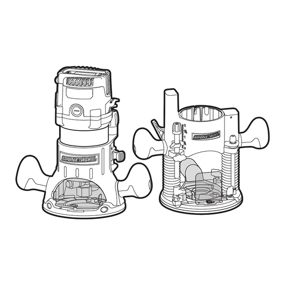
OVERVIEW Electronic keyboard LED display screen ON/OFF Power switch indicator Fine- adjustment dial Handle Depth-indicator ring 1 /6 4 3 /6 4 Motor clamp Spindle lock Dust- extraction Chip shield Base 1/2” Lock nut LED worklight Coarse- adaptor plate collet adjustment button Plunge-depth locking lever... -
Page 9: Assembly
SPECIFICATIONS Rated voltage 120 V~ 60 Hz Rated power Input 14 A Max HP 2.5 HP Speed 10,000–25,000 RPM Collet capacity 1/4” & 1/2” Fixed-base range 1-3/4” Plunge stroke 2” Base dimension Fixed base 6”; Plunge base 6-11/16” Inside base diameter 2”... - Page 10 ASSEMBLY SELECTING THE CUTTER BIT FIG. 2 1/4” collet This router comes with 1/2”collet and 1/4” sleeve collet sleeve that accept cutter bits with 1/2” and 1/4” shanks, respectively. The 1/2” collet is equipped on the tool, the 1/4” collet sleeve can be installed inside the 1/2”...
- Page 11 ASSEMBLY INSTALLING MOTOR IN FIXED FIG. 3 BASE (FIG. 4) Cutter Bit shank FIG. 4 Spindle-lock button Coarse- adjustment Arrow button Motor clamp 7. With the cutter bit inserted and the spindle-lock button pressed engage the shaft, place the wrench on the collet and turn it clockwise until the WARNING: Never use the router...
- Page 12 ASSEMBLY INSTALLING MOTOR IN PLUNGE REMOVING MOTOR FROM THE BASE (FIG. 5) PLUNGE BASE (FIG. 5) FIG. 5 1. Disconnect the plug from the power supply. 2. Place the router on a flat surface. 3. With the back of the plunge base facing you, open the motor clamp and make Arrow sure that the plunge action is in the...
- Page 13 ASSEMBLY INSTALLING THE DUST-EXTRAC- HEAVY-DUTY EDGE GUIDE (FIG. 7) TION ADAPTORS (FIG. 6) FIG. 7 Edge-guide FIG. 6a adjustment button Fixed base 1 / 6 4 3 /6 4 Lock nut Dust-extraction The router combo kit comes with a heavy- adaptor duty edge guide.
-
Page 14: Operation
OPERATION INSTALLING THE PATTERN NOTICE: All depth adjustments on the fixed base must be made with the motor GUIDE (FIG. 8) clamp open. NOTICE: For fixed base routers, the cutter To attach the pattern guide onto either the bit depth equals the amount of the cutter fixed or plunge base, position and secure it that is exposed below the surface of the to the base with the screws (included);... - Page 15 OPERATION DEPTH ADJUSTMENT WITH THE FIG. 10 PLUNGE BASE PLUNGING ACTION (FIG. 11) 1/ 64 3/ 64 FIG. 11 5. Turn the fine-adjustment dial clockwise to lower the bit to the desired depth of cut. Turn the dial counterclockwise to raise the cutter bit.
- Page 16 OPERATION PLUNGE ACTION WITH DEPTH- 7. Unlock the plunge depth-locking lever to allow the bit to automatically retract STOP ROD AND DEPTH-STOP to the up position. TURRET (FIG. 12) 8. The desired depth-of-cut may now be achieved by plunging the router down until the depth-stop rod contacts the FIG.
- Page 17 OPERATION MICRO-ADJUSTMENTS WITH TOGGLE “ON/OFF” THE DEPTH-STOP ROD AND SWITCH (FIG. 14) DEPTH-STOP TURRET FIG. 14 The depth-stop rod has a micro-adjustment knob that turns a screw (inside the rod) either clockwise or counterclockwise to lower or raise the depth-stop rod on the turret for 1 /6 4 3 /6 4 micro-fine adjustments of the plunge depth.
- Page 18 OPERATION LED WORKLIGHTS (FIG. 15) ELECTRONIC VARIABLE-SPEED CONTROL (FIG. 17) FIG. 15 FIG. 17 Your router motor has 3 built-in worklights located around the collet to provide high The electronic-speed control feature allows visibility of the workpiece when cutting. the motor speed to be matched to the These lights are always “On”...
- Page 19 OPERATION DIAL FIG. 18 APPLICATION SETTING 10,000/11500 Hardwoods, larger 13,000/14500 diameter 1/ 64 3/ 64 cutter bits 16,000/17500 19,000/20500 Softwoods, plastics, countertops, 22,000/23500 smaller diameter 25,000 cutter bits NOTICE: Reduce the speed when using EDGE ROUTING (FIG. 19) very large bits (1-inch or greater in cutting diameter) or heavy cutting bits.
- Page 20 OPERATION 6. Unplug the router from the power 5. Unplug the router from power source, source, and inspect the finished cut. place the router upside down on the worktable, and inspect the finished cut WARNING: Always securely clamp in the workpiece. your workpiece and keep a firm grip on WARNING: the router base with both hands at all...
- Page 21 OPERATION 5. When the cutter bit comes to a complete When freehand routing: stop, unlock the plunge-lock lever (Up) 1. Draw or lay out the pattern on the and the plunge action will automatically workpiece. retract the cutter bit from workpiece. 2.
- Page 22 OPERATION TOP EDGE SHAPING (FIG. 23) extends beyond the edge of the workpiece), the bit will make less than a full cut - which will alter the shape of the finished edge. FIG. 23 Motor housing NOTICE: The size (diameter) of the pilot Spindle lock that is used determines the maximum cut width that can be made with the pilot...
- Page 23 OPERATION DIRECTION OF FEED - EXTER- KICKBACK NAL CUTS (FIG. 25) Because of the high speed of the cutting bit during a proper feeding operation (left The cutter bit rotates clockwise. (When to right), there is very little kickback under installed on a router table, the rotation is normal conditions.
- Page 24 OPERATION FEEDING TOO RAPIDLY (FIG. 28) When the guide is positioned on the right-hand side of the router, the router travel should be from left to right and FIG. 28 counterclockwise around curves (FIG. 26). Bit shank This counterclockwise action around the curve could cause “Climb cutting”.
- Page 25 OPERATION FEEDING TOO SLOWLY (FIG. 29) When you feed the cutting bit too slowly, the rotating cutting bit does not cut into new wood rapidly enough to take a bite. Instead, FIG. 29 it scrapes away sawdust-like particles. This scraping produces heat, which can glaze, Bit shank burn, and mar the cut in the workpiece and, in extreme cases, overheat the cutting bit.
-
Page 26: Maintenance
MAINTENANCE Before cleaning performing NOTICE: To reinstall the same brushes, maintenance, verify that the router has been make sure that the brushes go back in the disconnected from the power supply. Keep same way they came out. This will avoid all ventilation openings clean. -
Page 27: Troubleshooting
TROUBLESHOOTING PROBLEM CAUSE SOLUTION The router does Plug is not plugged into the Plug the cord into the power source. not work. power source. Switch is in “OFF” position. Move the switch to “ON” position. The carbon brushes have Remove the brush caps and replace the worn out completely. - Page 28 NOTES Page 27...
- Page 29 NOTES Page 28...
- Page 30 NOTES Page 29...
-
Page 31: Warranty
90-DAY MONEY BACK GUARANTEE: This MASTERFORCE brand power tool carries our 90-DAY Money Back ® Guarantee. If you are not completely satisfied with your MASTERFORCE brand ® power tool for any reason within ninety (90) days from the date of purchase, return... - Page 32 © 2016 Menard, Inc., Eau Claire, WI 54703 08/2016...
Need help?
Do you have a question about the 241-0835 and is the answer not in the manual?
Questions and answers