
Related Manuals for Telemetrics PT-HP-S4

Summary of Contents for Telemetrics PT-HP-S4
- Page 1 Operation Manual HP Servo P/T Head (48V) Model PT-HP-S4 92 56156 000 P/N 92 56156 000-11 Rev. A 6 Leighton Place Mahwah, New Jersey 07430 www.telemetricsinc.com...
-
Page 2: Table Of Contents
Serial Data Connection ..........................3 Auxiliary Connections ...........................4 Camera Power & Camera Control................4 Lens Interface Information..................8 Connector Input/Output Signals ................9 PC Boards ......................13 APPENDIX A Telemetrics Serial Data Protocol............. 15 APPENDIX B Controller Board 53915 DIP Switch Setting ..........28... - Page 3 List of Figures Figure 1. Pan/Tilt Head....................1 Figure 2 Power Cable CA-PWR-7XLR- XXX ..............3 Figure 3 Serial Data Cable ................... 3 Figure 4. Trolley/Televator Cable CA-S2-AUX............. 4 Figure 5 Sony DXC-950/990 Power Cable ..............5 Figure 6 Sony DXC-950/990 Data Cable ..............5 Figure 7 Sony DXC-950/990 Power/Data Cable............
- Page 4 LITHIUM BATTERY CAUTION, Danger of explosion if the internal lithium battery is replaced incorrectly. Replace only with the same or equivalent type recommended by the manufacturer. Dispose of used batteries according to the battery manufacturer’s instructions. The Lightning Flash With Arrowhead symbol, within an equilateral triangle, alerts the user to the presence of uninsulated dangerous voltage within the product’s enclosure that may be of sufficient magnitude to constitute a risk of electric shock.
-
Page 5: Scope
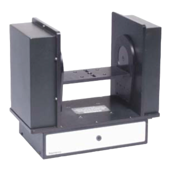
1.0 Scope This manual contains information for the Telemetrics HP Servo Pan/Tilt Head Model PT-HP-S4, Part No. 92 56156 000. This Pan/Tilt is designed for use with ENG and smaller type cameras. Due to the different types of cameras and lenses the Pan/Tilt interfaces with, many options are manufactured. -
Page 6: Specifications
3.0 Specifications Input voltage 38-53VDC Input current 6.8 A max Input Power 50 W (P/T head only) Input Power Conn. 7-pin Male XLR Camera Power 40 W (13.5 VDC, 3 A max) Pan travel ±170° w/endstops, ±200° w/o endstops Tilt travel ±35°... -
Page 7: System Cables
4.0 System Cables 4.1 Power Cable Power to the unit is made via interconnect cable CA-PWR-7XLR-XXX to the 7-pin XLR power connector located on the rear of the unit (Note: XXX=Feet). The other end of interconnect cable connects to the external power supply. ALPHA #25836 QUABBIN #4177 +48V... -
Page 8: Auxiliary Connections
Figure 4. Trolley/Televator Cable CA-S2-AUX 5.0 Camera Power & Camera Control Telemetrics pan/tilt systems are capable of providing power and data to virtually all manufacturers’ cameras. A Telemetrics power supply that includes a 15V module for the camera must be used when camera power is required. In addition, the Telemetrics control panel must be configured to accept the camera ROP to provide camera control. -
Page 9: Figure 5 Sony Dxc-950/990 Power Cable
Figure 5 Sony DXC-950/990 Power Cable Figure 6 Sony DXC-950/990 Data Cable... -
Page 10: Figure 7 Sony Dxc-950/990 Power/Data Cable
Figure 7 Sony DXC-950/990 Power/Data Cable Figure 8. Panasonic AW-E600/800 Power Cable Figure 9. Panasonic AW-E600/800 Data Cable... -
Page 11: Figure 10. Panasonic Aw-E600/800 Power/Data Cable
Figure 10. Panasonic AW-E600/800 Power/Data Cable Figure 11. Hitachi HV-D15 Power Cable Figure 12. Hitachi HV-D15 Power/Data Cable... -
Page 12: Lens Interface Information
Pan/Tilt, simply plug lens controls pendant into the Pan/Tilt lens connector. NOTE If the controller is a Telemetrics preset system, additional modifications must be performed to bring the focus and zoom positional voltages out of the lens. Please refer to preset controller manual for complete instructions. -
Page 13: Connector Input/Output Signals
7.0 Connector Input/Output Signals Controls 9 Pin D Type Mating View of Pin Assignment Bulkhead 9 Pin D Female RS-232 1 Reserved * 6 No Connection 2 TX Data (From P/T) 7 No Connection 3 RX Data (to P/T) 8 No Connection 4 Reserved * 9 No Connection 5 Ground... - Page 14 Lens 12 Pin Male Type Mating View of Bulkhead 12 Pin 11 12 Pin Assignment Circular Male 1. Focus Mode 7. Lens Ref or Focus Ref. (Non- 2. Zoom Mode teleconferencing Lens) 3. Ground 8. Focus Control 4. Iris L/C 9.
- Page 15 Tally 12 Pin Female Type Mating View of Bulkhead 12 Pin Pin Assignment Circular Female 1. N/C 7. N/C 2. N/C 8. N/C 3. Tally- 9. N/C 4. N/C 10. N/C 5. N/C 11. N/C 6. Tally+ 12. N/C Ethernet RJ 45 Type Mating View Pin Assignments...
-
Page 16: Pc Boards
8.0 PC Boards 8.1 Controller Board 53915 53915... - Page 17 Table 1 Pan/Tilt 53915 Bd DIP-Switch Description (S1) DESCRIPTION PAN DIRECTION UPRIGHT INVERTED TILT DIRECTION UPRIGHT INVERTED TRACK DIRECTION NORMAL REVERSE ZOOM DIRECTION LENS SPECIFIC LENS SPECIFIC FOCUS DIRECTION LENS SPECIFIC LENS SPECIFIC IRIS DIRECTION LENS SPECIFIC LENS SPECIFIC AUXILIARY DIRECTION NORMAL REVERSE RS232/RS422 RS422...
-
Page 18: Appendix A Telemetrics Serial Data Protocol
The Telemetrics Inc. S2 Serial Protocol Users Manual is copyrighted with all rights reserved. Copyright of this manual belongs to Telemetrics Inc. No part of this manual, including the products and software described in it may be reproduced, transmitted or translated into any language in any form or by any means without written permission of Telemetrics Inc., except for backup or archival purposes. - Page 19 Telemetrics provides for serial control of many of our camera control products. This summary briefly describes the protocol for serial control of these devices. In the summary, the Telemetrics controlled device will be referred to as the “controller” and the device commanding the controller will be referred to as the “host”.
- Page 20 Manual Camera Motion The procedure for manually moving a camera is as follows: • Reset motion voltages with the ‘R’ command. • Move the camera using ‘P’, ‘T’ “Z’ and ‘F’ commands. The following 2 sections discuss the commands used. Camera Control Voltages Camera motion is controlled by four voltages corresponding to the velocity of pan, tilt, zoom and focus which are set using the ‘P’, ‘T’...
- Page 21 Preset Position Control There are 64 preset positions, numbered 0 to 63, available in the controller’s non- volatile memory. The information stored in a preset location does not include the camera to which the preset corresponds. Therefore, it is up to the host application to select the proper camera to be used prior to preset operations The normal method for preset control is as follows: •...
- Page 22 Preset Recalling Commands The ‘C’ command recalls the preset position stored in the preset number given as its parameter. As noted earlier in this document, once the controller begins a recall command, any control commands remaining on the command line are ignored. While the recall is in progress, the only character that will be acted upon is the <CAN>...
- Page 23 Command Summary Request Commands COMMAND RETURN PARAMETERS DESCRIPTION ± 2147483647 (± 2 Current Pan Position ± 2147483647 (± 2 Current Tilt Position 0 – 1024 (2 Current Zoom Position 0 – 1024 (2 Current Focus Position ± 2147483647 (± 2 Current Trolley/Pedestal Position ±...
- Page 24 PWM Commands COMMAND PARAMETERS DESCRIPTION ± 255 (± 2 Set Pan PWM Drive (-255 = R ; 0 = STOP ; 255 = ± 255 (± 2 Set Tilt PWM Drive (-255 = D ; 0 = STOP ; 255 = ±...
- Page 25 COMMAND PARAMETERS DESCRIPTION @VEL= * see desc. Show Axis Velocity Settings (P=1,T=2,X=3,Z=4,F=5,I=6,Y=7) @LVEL * see desc. Load Axis Default Velocity Settings (P=1,T=2,X=3,Z=4,F=5,I=6,Y=7) @?JVH 0-2147483647 Set Axis Maximum Velocity for Joystick Controls @?JVL 0-2147483647 Set Axis Minimum Velocity for Joystick Controls @?PVH 0-2147483647 Set Axis Maximum Velocity for Preset Fade Shots...
- Page 26 Velocity & Acceleration Settings Commands COMMAND PARAMETERS DESCRIPTION @PID= * see desc. Show Axis PID settings (P=1, T=2, X=3, Y=7) @SET= * see desc. Burn Axis PID settings (P=1, T=2, X=3, y=7) @LPID * see desc. Load Axis Default PID settings (P=1, T=2, X=3, y=7) @?KP= 0-32767 Set Axis KP (Proportional Gain)
- Page 27 Misc Setup Commands COMMAND PARAMETERS DESCRIPTION @PROG 1010 Upload New Firmware to Flash @INIT 1010 Initialize Servos @ZERO 1010 Reset Positions and Calibrate Lens @REFS 1010 Report Digital Pot Settings for Zoom & Focus @ZREF 0-255 Set Digital Pot for Zoom @FREF 0-255 Set Digital Pot for Focus...
- Page 28 Please note the DIP-Switch state in the pan/tilt head. There is a software package available to download the lens configuration to the pan/tilt head. Please contact Telemetrics for more information. Zoom Zoom Pot (V)
- Page 29 Aux Axis Soft Limit Configuration The aux axis (trolley, Televator, elevating pedestal) has the ability to smoothly stop before hitting the mechanical end stop. This software limit can be setup using the command protocol. 1. Set the lower and upper windows. The windows represent the number of counts from the physical stop, the soft limit.
- Page 30 Pan/Tilt DIP-Switch Description DESCRIPTION PAN DIRECTION UPRIGHT INVERTED TILT DIRECTION UPRIGHT INVERTED TRACK DIRECTION STANDARD REVERSED ZOOM DIRECTION LENS SPECIFIC LENS SPECIFIC FOCUS DIRECTION LENS SPECIFIC LENS SPECIFIC IRIS DIRECTION LENS SPECIFIC LENS SPECIFIC AUX-Y DRIECTION STANDARD REVERSED RS232/RS422 RS422 RS232 Show Axis Velocity/Acceleration Settings The SHOW AXIS VELOCITY commands reports the settings for the specified axis.
-
Page 31: Appendix B Controller Board 53915 Dip Switch Setting
APPENDIX B Controller Board 53915 DIP Switch Setting If the Controller Board 53915 revision, indicated in the revision box, is P or higher, for DIP switch setting follow the instructions below: 1. DIP Switch 1, positions 1 to 7 – use as described in Appendix A. 2. - Page 32 Repair Request RA# Please fill in completely. All parts are required. Equipment not accompanied by completed paperwork will be returned unrepaired at your expense. Technical Contact/Ship To Billing Contact Name Address 1 Address 2 City State ...
Need help?
Do you have a question about the PT-HP-S4 and is the answer not in the manual?
Questions and answers