
Related Manuals for Heat Controller Comfort-Aire BHD-301-D


Summary of Contents for Heat Controller Comfort-Aire BHD-301-D
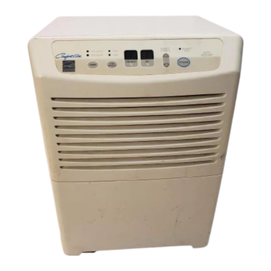
- Page 1 HEAT CONTROLLER, INC. Dehumidifier MODELS: BHD-301-D BHD-501-D BHD-651-D Service Manual CAUTION -Before servicing the unit, read the "safety precautions" in this manual. -Only for authorized service personnel.
-
Page 2: Table Of Contents
CONTENTS 1. PREFACE 1.1 SAFETY PRECAUTIONS ...........................3 1.2 FEATURES AND DIMENSIONS ........................3 1.2.1 FEATURES............................3 1.2.2 DIMENSIONS ............................3 1.3 SPECIFICATIONS ............................4 1.4 CONTROL TYPE ............................5 1.4.1 MECHANICAL TYPE.........................5 1.4.2 ELECTRONIC TYPE .........................5 1.5 HOW TO OPERATE DEHUMIDIFIER ......................6 1.5.1 HOW DOES THE DEHUMIDIFIER WORK? ..................6 1.5.2 LOCATION FOR THE DEHUMIDIFIER.....................6 1.5.3 MICRO SWITCH..........................6 1.5.4 AUTO DEFROST..........................6... -
Page 3: Preface
1. PREFACE This Service Manual provides various service information, including the mechanical and electrical parts. This dehumidifier was manufactured and assembled under the strict quality control procedures. The refrigerant is charged at the factory. Be sure to read the safety precaution prior to servicing the unit. 1.1 SAFETY PRECAUTIONS •... -
Page 4: Specifications
1.3 SPECIFICATIONS MODELS BHD-301-D BHD-501-D BHD-651-D ITEMS CAPACITY(Pints/24hrs) POWER SUPPLY(Phase,V,Hz) 1Ø, 115V,60Hz INPUT(W) RUNNING CURRENT(A) ENERGY FACTOR(L/kw.h) 1.80 REFRIGERANT REFRIGERANT CHARGE, oz(g) 5.29(150) 7.23(205) 8.82(250) THERMISTOR OPEN 33.8˚F(1±0.5°C) CLOSE 50˚F(10±0.5°C) SOLENOID VALVE Using Temp/Humid.:-4~122˚F(-20~50°C)/95%RH Rating:7W/90mA COMPRESSOR MODEL No. SD063SW YZG-A17D2T2... -
Page 5: Control Type
1.4 CONTROL TYPE 1.4.1 Mechanical type Humidity Control • When you first use the dehumidifier, turn the humidity control to 5 or 6. If you still have moisture, turn the humidity control to a higher setting. High MAX is the highest setting. •... -
Page 6: How To Operate Dehumidifier
1.5 HOW TO OPERATE DEHUMIDIFIER 1.5.1 HOW DOES THE DEHUMIDIFIER WORK? Motor Moist, humid air is drawn over a cold refrigerated Condenser Evaporator dehumidifying coil. Moisture in the air condenses on this coil and drains into a bucket (or through the bucket into a Humid hose and drain). -
Page 7: Humidity Controller
1.5.5 HUMIDITY CONTROLLER 5(42%) 42% R.H 1.5.5.1 Mechanical Type 4(50%) 6(35%) The humidity control can be set anywhere between Off and Max for normal operation. 3(60%) 7(30%) If you need more dehumidification, turn the Humidity Control toward Max. If you need less dehumidification, turn the Humidity Control toward Off. -
Page 8: Circuit Diagram
2. CIRCUIT DIAGRAM • MODEL : BHD-301-D PART NO. Q'TY DESCRIPTION PER SET MARKS BHD-301-D 6411A20001Z POWER CORD ASSEMBLY 6600FX5001G SWITCH, ROCKER 4681A20040Q MOTOR ASSEMBLY 0CZZA20005J CAPACITOR TBZ31986001 COMPRESSOR, SET EAF35787201 6871A20289B PWB(PCB) ASSEMBLY, DISPLAY 6877A30013R SENSOR ASSEMBLY 6601A30006A SWITCH ASSEMBLY, ROTARY... - Page 9 • MODEL : BHD-501-D/BHD-651-D WIRING DIA GRAM MAIN PCB CN-FAN BK(HI) RD(LOW) MOTOR OR(COM) GN/YL CN-AC1 WH(BL) (N) BUCKET CN-AC2 CN-SEN HUMIDITY GN/YL SENSOR COMP. POWER RY-COMP SMPS THERMISTOR FUSE 250V T3.15A O.L.P BK(BR) (L) 3854A2024 0247Z PART NO. Q'TY DESCRIPTION PER SET MARKS...
-
Page 10: Disassembly Instructions
3. DISASSEMBLY INSTRUCTIONS 3.1 MECHANICAL PARTS 3.1.1 BUCKET AND AIR FILTER 1. Turn the Humidity Control off(Mechanical type) or press the power button off. (Electronic type) 2. Disconnect the power supply. 3. Remove the bucket. (See Figure 9) 4. Pull out the air filter. (See Figure 10) Figure 9 Figure 10... -
Page 11: Control Parts
3.2 CONTROL PARTS 3.2.1 POWER CORD ASSEMBLY 1. After opening the control box, remove the screw that holds the ground wire. (See Figure 15) 2. Disconnect the remaining leads of the power cord from the PWB(PCB) ASSEMBLY, MAIN, then remove it from the control box. Figure 15 3.2.2 SENSOR ASSEMBLY 1. -
Page 12: Control Panel
3.2.6 CONTROL PANEL 3.2.6.1 CONTROL PANEL - Mechanical Type (BHD-301-D) 1. Disconnect housing and all leads of the rocker switch, SWITCH ASSEMBLY, ROTARY and PWB(PCB) ASSEMBLY, DISPLAY from PWB(PCB) ASSEMBLY, MAIN (3.1.3) 2. Pull out the knob assembly. 3. Remove the nut which fastens the SWITCH ASSEMBLY, ROTARY. -
Page 13: Fan And Motor
3.2.7 FAN AND MOTOR 1. Turn the nut left and full out the Fan by hands carefully. 2. Remove 2 screws that fasten Heat Exchange. 3. Lift the H/E and open the H/E around 45 degree clockwise carefully. (See Figure 21) 4. -
Page 14: Refrigerating Cycle
3.3 REFRIGERATING CYCLE 3.3.1 CONDENSER, EVAPORATOR AND CAPILLARY TUBE 1. Remove the insulation on the Heater/Evaporator (H/E) assembly 2. Pierce the pinch-off tube to discharge the refrigerant, using a refrigerant recovery system. 3. After discharging the refrigerant completely, remove 2 screws between the housing assembly and the H/E. -
Page 15: How To Replace Refrigeration System
3.4 HOW TO REPLACE THE REFRIGERATION SYSTEM 1. When replacing a refrigeration component, be sure 7. Recharge as follows : to discharge the refrigerant system by using a 1) Refrigeration cycle systems are charged from the refrigerant recovery system. High-side. If the total charge cannot be put 2. - Page 16 Equipment needed: Vacuum pump, charging cylinder, manifold gauge, brazing equipment. pinch-off tool capable of making a vapor-proof seal, leak detector, tubing cutter, hand tools to remove components, service valve. EVAPORATOR ASSEMBLY (LOW PRESSURE SIDE) CONDENSER ASSEMBLY (HIGH PRESSURE SIDE) COMPOUND GAUGE MANIFOLD GAUGE CAPILLARY...
-
Page 17: Troubleshooting Guide
4. TROUBLESHOOTING GUIDE CONDITION CAUSE REMEDY 1. Dehumidifier does not start. (Both No power Check power supply at outlet. compressor and fan motor do not Correct if none. operate.) Poor plug contact at outlet. Install plug properly or replace it. Bucket is full. - Page 18 CONDITION CAUSE REMEDY 5. Noisy operating If cracked, out of balance, or partially missing, replace it Loose foreign material inside the housing. Remove it. Tube hits frame. Adjust tubing routine carefully. Fan blade hits frame Check Motor Mount. If loose, tighten it. Internal compressor noise.
-
Page 19: Exploded Views
5. Exploded View • MODEL:BHD-301-D W0CZZ-2 149980 349600 554030 354210 268711-2 359012 264110 249950 346811 435300 131400 165010 135312 266002 238310 149410 268711-1 436500 266003 352113 235512 35211A 152302 266010 552111 752140 330870 567502 130410 554160 144410 148391 550140 — —... - Page 20 • MODEL:BHD-501-D W0CZZ-2 149980 349600 554030 354210 W0CZZ 359012 268711-2 249950 346811 435300 264110 131400 165010 135312 238310 235512 268711-1 436500 352113 35211A 152302 266010 552111 752140 330870 567502 130410 554160 144410 550140 148391 — — —20—...
- Page 21 • MODEL:BHD-651-D W0CZZ-2 149980 349600 554030 W0CZZ 359012 354210 268711-2 249950 346811 435300 264110 131400 165010 135312 238310 235512 268711-1 436500 552111 35211A 152302 266010 352113 752140 330870 567502 130410 554160 144410 550140 148391 — — —21—...
-
Page 22: Replacement Parts List
6. REPLACEMENT PARTS LIST • MODEL: BHD-301-D LOCATION PARTNO DESCRIPTION REMARK BHD-301-D 130410 Base Assembly,Single 3041A10042E 144410 Roller 4441A30001B 149980 Shroud 4998A10034B 266010 Switch Assembly 6600A30003C 330870 Pan Assembly,Drain 3087A10019C 349600 Bracket,Motor 4960A20009B 550140 Washer,Customized 1WZZA31003A 554160 Compressor Set,China TBZ31986001... - Page 23 • MODEL: BHD-501-D PART NO LOCATION DESCRIPTION REMARK BHD-501-D 130410 Base Assembly,Single 3041A10042A 131400 Cabinet 3090A10042G 135312 Grille Assembly,Front AEB36976502 144410 Roller 4441A30001B 148391 Tank Assembly,Bucket 4839A10002F 149980 Shroud 4998A10034B 152302 Filter,Air 5230A20040A 165010 Sensor Assembly 6877A30013R 235512 Cover Assembly,Display 3551A20109C 238310 Escutcheon...
- Page 24 • MODEL: BHD-651-D LOCATION PART NO DESCRIPTION REMARK BHD-651-D 130410 3041A10042A Base Assembly,Single 131400 3090A10042G Cabinet 135312 AEB36976502 Grille Assembly,Front 144410 4441A30001B Roller 148391 4839A10002F Tank Assembly,Bucket 149980 4998A10034C Shroud 152302 5230A20040A Filter,Air 165010 6877A30013R Sensor Assembly 235512 3551A20109C Cover Assembly,Display 238310 MDD30271508 Escutcheon...
- Page 25 MEMO —25—...
- Page 26 MEMO —26—...
- Page 27 Specifications and performance data subject to change without notice. HEAT CONTROLLER, INC. 1900 WELLWORTH AVENUE • JACKSON, MICHIGAN 49203 THE QUALITY LEADER IN CONDITIONING AIR P/No.: MFL38891301...
Need help?
Do you have a question about the Comfort-Aire BHD-301-D and is the answer not in the manual?
Questions and answers