Table of Contents
Advertisement
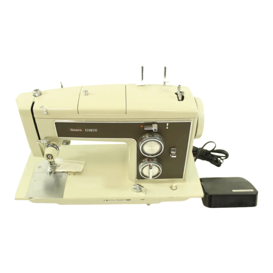
158.17572
158.17560
158.17740
158.17570
158.17741
1S8.17S71
STRAIGHT STITCH
ATTACHMENT
ZIGZAG BITE
FOOT CONTROL
POSITION
DIMENSION
ml
(;ENTER
LO1€ BAR
_,8
6816
ii
PRESSERFOOT HEIGHT
LOW BARTYPE
•_136
MM
MINIMUM
5.2 MM
NEEDLEPLATESURFACE
HIGH BARTYPE
24 S MM
MINIMUM
8.2 MM
SUPERHIGH OARTYPE
...... . NllOM
5.2 MM
FRONT FACING SHUTrLE
SIDE FACING SHUTrLE
SUPER HIGH BAR
LOW BAR
HIGH BAR
LOW BAR
Drop feed dog Pressdo_ pressure
regulator
t o the max,mumpressure Lowerpressurefoot lever Loosenthumbscrewend be
sure presser foot t,* seated properly Tighten
thumb
screw
If adjustment Is necessaw, raise presser foot lever and loosen screws on presser bar holder AdluSt the height of presserfoot
fror, r needle plate as _oecd,ad Coohrmthe he,oht of presser foot by a complete turn of the handwheel T,ghten the screws
securely after edlustment
Disldbuticm of Needle Swing
Set spe_al stitch dial at red "S" or ted dot and sUtch
width control at red "S"
or red dot. Using the
straight stitch needle plate, check and see if the
needle Sees in the center of the needle hole. If not,
adjust the needle poslUon according to inst_eUons
on I)-2.
Us_g
the _d_g
stitch
needle
plate, check the
needle swing by turning the stitch width control from
"S" or red dot to "4" with the needle at Its lowest
pooit/on (Step No. l). Next rotate hand wheel one
complete turn =nd check needle swing by turning
stitch width control from "S" or red dot to "4"' with
needle st its lowest position. (Step No. Z).
If needle swins in Step No. I is not equal to that in
Step No. 2, loosen screw (A), insert eccentric tool in
hole (B) and move adjustable
plate (C) in either
d/reetton (D) or (E) to obta/n equal needle swing.
After adjusting tighten screw (A).
,_..J
"8.c
FIGURE
C-le
Needle Pedtlen
Set stitch width control at 0. Prepare the needle plate
for straight
stitching
by revers/ng
or sliding
the
center plate (See Figures
l & 21 or place the needle
plate Insert for straight
stitch onto the needle plate
(See Figure 3). Tur'n_g handwheel,
check and see if
the needle goes through the needle hole at lteeenter.
If not, loosen nut (1) and adjust needle
posit/on by
sUShtly turnlnl
the eccentric
roller pin (3). TlShten
the nut securely
after adjustnlant.
FIGURE A-f
Advertisement
Table of Contents

Related Manuals for Kenmore 158.17560


Summary of Contents for Kenmore 158.17560
- Page 1 158.17572 158.17560 158.17740 Disldbuticm of Needle Swing 158.17570 158.17741 1S8.17S71 Set spe_al stitch dial at red "S" or ted dot and sUtch ,_..J width control at red "S" or red dot. Using the STRAIGHT STITCH ATTACHMENT ZIGZAG BITE FOOT CONTROL...
-
Page 2: Feed Dog Height
158.17560 I_IWwwIIIN I 158.17570 158.17571 158.17572 SET SPECIAL STITCH DIAL AT "S". STITCH WIDTH CONTROLAT Feed Dog Height "S" AND STITCH LENGTH CONTROLAT "0". TURNING HANDWHEEL, 158.17740 CHECK TO SEE IF THE FEED DOG ROVES HORIZONTALLY. AT THIS 158.17741 POSITION THE FEEO DOG SHOULD NOT ROVE. -
Page 3: Needle Timing To Shuttle Needle Bar Height
NEEDLE TIMINGTOSHUTTLE NEEDLE TIMING TO SHUTTLE Do not attemptidlustmlntsotherthan thosespecdled m this manualH. byfollowing the prescnbed procedures. :t is NEEDLE BAR HEIGHT determinedthat | machine ISout of radialtime.handlepet Bulletin S.R20 Radial Timing Gauge THE RADIAL TIMING GAUGESAND TEST PINS, Instructions ILLUSTRATED BELOW, ARE AVAILABLE FROMDIVISION 92, SOURCE192. -
Page 4: Needle Clearance To Shuttle
Needle €learance te Shulde 158.17560 158.17570 The Cf¢sran¢_ "'a.'" °'b." "c," the angle "d" are yew 158.17571 critical po_ttlS ,n relatiOn tO fill needle t,mln 9 to shuttJe. Hoverer. the_l _)omts _rl v,sual(y _terml_d by J$1_ the 158.17572 Rjdlal Timing G,tugls. -
Page 5: Streight Stitching/Automatic Reverse Stitching
158.17560 Stmil_t Stitching 158.17570 158.17571 158.17572 158.17740 SET STITCH wIDTH CONTROL AT "S". TURNIkR_HANDWHEEL SLOWLY, CHECK TO SEE IF THE NEEDLE SWINGS. IT SHOULD 158.17741 NOT SWING. IF ADJUS'YMENT IS NECESSAR_ LOOSEN SCREW (1) AND MOVE THE ZIGZAG WIDTH ARM (2) TO THE EXTREME LEFT POSITION. -
Page 6: Cam Selectorguide Plate Setting
Cam Selecter Guide Plate Setting Remove the cap on the backside of the machine arm and loosen ll_'r_ (A) with a acrew ¢h'tTer U the cam follower does not a_llrn with the cam tlu'o_ih the hole of the machine arm. l_lhinlr adJtmt In the _ollowinl_ manner.
Need help?
Do you have a question about the 158.17560 and is the answer not in the manual?
Questions and answers
I bought a used kenmore module 158.17550 and I am missing the owners manual the bobbin case and needles.