dbx DriveRack Monitor Application Manual
Complete equalization and loudspeaker management system
Hide thumbs
Also See for DriveRack:
- User manual (52 pages) ,
- User manual (51 pages) ,
- User manual (49 pages)
Advertisement
Quick Links
Advertisement

Related Manuals for dbx DriveRack


Summary of Contents for dbx DriveRack
-
Page 2: Table Of Contents
DriveRack™ Monitor Application Guide Table of Contents Welcome..............3 Defining the DriveRack™ System......3 Applications ............6 Making Connections..........10 Crossover Block Diagrams........21 Specifications ............26 ®... -
Page 3: Welcome
DriveRack™ unit(s) in a Monitor Application. Defining the DriveRack™ System The dbx DriveRack™ Loud Speaker Management System is the most effective way to manage all aspects of post mix processing and signal routing. The following are just some of the features of the 480, 481, 482 and 480R DriveRack™... - Page 4 • RS-232 GUI Interface for computer display and configuration 480R DriveRack™ features: • Dedicated remote interface to control all 480, 481 and 482 DriveRack™ units • 31 Motorized faders for equalization control • 32 assignable hot-keys with up to 64 different assignment capabilities •...
- Page 5 Dual RTA analyzers can be run simultaneously with RTA source inputs capable of being remote- ly switched on the fly. The 480 DriveRack™ is fully programmable from the front panel, and can control other devices in a network including the 481 and 482. The entire system can be controlled via the 480R DriveRack™...
-
Page 6: Applications
2) DriveRack™ on Inserts (EQ only) To use the DriveRack™ on inserts as an EQ only unit, simple patch into 4 insert points on the con- sole and select a full range x-over on each of the input channels. This gives you four 31-band graphic EQs or four 9-band parametric EQs per input as well as all the delay, phase, and com- pressor/limiter functions with using the x-overs. - Page 7 DriveRack™ Monitor Application Guide 1. DriveRack™ on Outputs (X-over and EQ) 2. DriveRack™ on Inserts (EQ only) ®...
- Page 8 DriveRack™ Monitor Application Guide 3. DriveRack™ on outputs (X-over only) 4. DriveRack™ on both inserts and Outputs (EQ and X-over) ®...
- Page 9 DriveRack™ Monitor Application Guide ®...
-
Page 10: Making Connections
This input network connection is used to receive information being sent from other units in the DriveRack™ network link. RS485 Control Thru Bus (DB-9 connector type) This Thru network connection is used to pass information to other units in the DriveRack™ net- work link. RS485 Control Bus Input (RJ-45 connector type) This input network connection is used to receive information being sent from other units in the DriveRack™... - Page 11 Inputs 3 and 4 offer Line/RTA switches that allow you to run a real time audio analyzer micro- phone directly into the input of the 480 DriveRack™. The four XLR inputs of the 480 Drive also offer Pin 1 lift switches which lift the ground of the selected XLR input when pressed.
- Page 12 This input network connection is used to receive information being sent from other units in the DriveRack™ network link. RS485 Control Thru Bus (DB-9 connector type) This Thru network connection is used to pass information to other units in the DriveRack™ net- work link. RS485 Control Bus Input (RJ-45 connector type) This input network connection is used to receive information being sent from other units in the DriveRack™...
- Page 13 These LEDS indicate when network is properly terminated. The Green LED indicates that the net- work has been correctly terminated. Remote Controller In Connection This DB-9 type input connection is used to receive information from the 480 Remote DriveRack™ Unit. Outputs 1-8 (Euroblock Connectors) The output section of the 481 DriveRack™...
- Page 14 This input network connection is used to receive information being sent from other units in the DriveRack™ network link. RS485 Control Thru Bus (DB-9 connector type) This Thru network connection is used to pass information to other units in the DriveRack™ net- work link. RS485 Control Bus Input (RJ-45 connector type) This input network connection is used to receive information being sent from other units in the DriveRack™...
- Page 15 Inputs 3 and 4 offer Line/RTA switches that allow you to run a real time audio analyzer micro- phone directly into the input of the 482 DriveRack™. The four XLR inputs of the 482 DriveRack™ also offer Pin 1 lift switches which lift the ground of the selected XLR input when pressed.
- Page 16 The threshold meters indicate that the threshold level has been exceeded within the dynamics sec- tion (compressor/limiter), and gain reduction is taking place within the specific output channel. Output Meters The 482 DriveRack™ provides the user with eight independent 12-seg- ment lightpipe™ output meters that range from -30 to +22 dBu. Output Mutes The eight output mute buttons are used for independently muting each output of the 482 DriveRack™.
- Page 17 This input is used to insert a microphone for use with the real time audio analyzer. Phantom Power Switch This Thru network connection is used to pass information to other units in the DriveRack™ net- work link. MIDI In and Out/Thru Connectors These connectors provide MIDI functionality to the 480 DriveRack™.
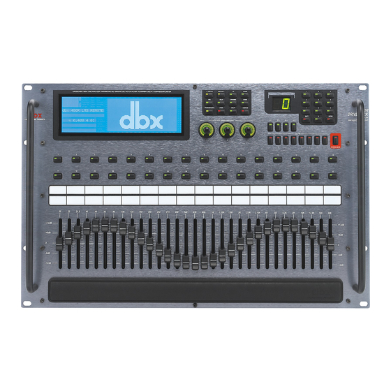
- Page 18 Monitor Application Guide Front Panel (480R) LCD Display The large LCD display of the 480R DriveRack™ provides the user with all of the vital process- ing information of the DriveRack™ including: signal routing, configuration modes, effect block editing and RTA displays.
- Page 19 Network Access Keypad This 12 button keypad is used to call up any one of the products that are used in a DriveRack™ network set up. Simply enter in the Id number of the device you wish to call up, and then hit the enter button.
- Page 20 Motorized Faders The 31 motorized faders of the 480R make editing and recalling EQ settings a breeze. The 31 faders control the graphic EQ of the currently selected channel of the selected DriveRack™. Rear Panel Connections (480P) IEC Power Cord Receptacle The 480P comes with switchable power supply that will accept voltages ranging from 100V-240V at frequencies from 50Hz-60Hz.
-
Page 21: Crossover Block Diagrams
DriveRack™ Monitor Application Guide Crossover Block Diagrams The following are crossover configurations found in the 480, 481 and 482 DriveRack™ units. ®... - Page 22 DriveRack™ Monitor Application Guide ®...
- Page 23 DriveRack™ Monitor Application Guide ®...
- Page 24 DriveRack™ Monitor Application Guide ®...
- Page 25 DriveRack™ Monitor Application Guide ®...
-
Page 26: Specifications
DriveRack™ Monitor Application Guide Specifications Specifications ( 480 DriveRack™) Inputs Number of Inputs: 4 (Inputs 3 or 4 can be selected as an RTA mic input) Connectors: Female XLR Type: Electronically balanced/RF filtered Impedance: >40kΩ Maximum Input Level:Hardware selectable for +30, +22, +14, dBu... - Page 27 Optional ROM Upgrade: Flash upgradeable through RS-232 Dimensions Dimensions: Height- 3.5” X Width- 19” X Depth 12.15” Specifications ( 481 DriveRack™) Inputs Number of Inputs: 4 (Inputs 3 or 4 can be selected as an RTA mic input) Connectors: Euroblock...
- Page 28 Reversible Miscellaneous Output Transformers: Optional Network: Proprietary RS-485 Backbone GUI: RS-232 interface for computer display and configuration Flying Fader Remote: Optional dbx 480R RTA Microphone: Optional ROM Upgrade: Flash upgradeable through RS-232 Dimensions Dimensions: Height- 1.75” X Width- 19” X Depth 7.90”...
- Page 29 DriveRack™ Monitor Application Guide Specifications ( 482 DriveRack™) Inputs Number of Inputs: 4 (Inputs 3 or 4 can be selected as an RTA mic input) Connectors: Female XLR Type: Electronically balanced/RF filtered Impedance: >40kΩ Maximum Input Level: Hardware selectable for +30, +22, +14, dBu...
- Page 30 Reversible Miscellaneous Output Transformers: Optional Network: Proprietary RS-485 Backbone GUI: RS-232 interface for computer display and configuration Flying Fader Remote: Optional dbx 480R RTA Microphone: Optional ROM Upgrade: Flash upgradeable through RS-232 Dimensions Dimensions: Height- 3.5” X Width- 19” X Depth 12.15”...
- Page 31 DriveRack™ Monitor Application Guide Specifications ( 480R Remote Controller DriveRack™) Inputs Number of Inputs: 1 Real Time Audio Analyzer Connectors: Female XLR Type: Electronically balanced/RF filtered Impedance: >40kΩ Max input RTA Level: -10 dBu CMRR: >40 dB typical, >55 dB at 1kHz...
- Page 32 8760 South Sandy Parkway • Sandy, Utah 84070 Phone: (801) 568-7660 • Fax (801) 568-7662 • Int’l Fax: (219) 462-4596 Questions or comments? E-mail us at: customer@dbxpro.com or visit our World Wide Web home page at: www.dbx- pro.com A Harman International Company MONITOR APPLICATION...
Need help?
Do you have a question about the DriveRack and is the answer not in the manual?
Questions and answers