Table of Contents
Advertisement
Advertisement
Table of Contents

Related Manuals for Furuno GP-31


Summary of Contents for Furuno GP-31
- Page 1 GPS NAVIGATOR DGPS NAVIGATOR GP-31/GP-36...
- Page 2 All rights reserved. All rights reserved. Printed in Japan Printed in Japan PUB.No. PUB.No. OME-43990 OME-43990 ( ( YOSH YOSH ) ) GP-31/36 GP-31/36 Your Local Agent/Dealer Your Local Agent/Dealer FIRST EDITION : FIRST EDITION : MAY. MAY. 1999 1999 : APR.
-
Page 3: Safety Instructions For The Operator
Immediately turn off the power at the switchboard if the equipment is emitting smoke or fire. Continued use of the equipment can cause fire or electrical shock. Contact a FURUNO agent for service. Keep heater away from equipment. A heater can melt the equipment’s power cord, which can cause fire or electrical shock. -
Page 4: Safety Instructions For The Installer
Safety Instructions for the Installer WARNING Do not open the cover unless totally familiar with electrical circuits and service manual. Improper handling can result in electrical shock. Turn off the power at the switchboard before beginning the installation. Fire or electrical shock can result if the power is left on. -
Page 5: Table Of Contents
9.4 Initial Settings ... 9-3 APPENDIX Menu Tree ... AP-1 Loran C Chains ... AP-3 Decca Chains ... AP-4 Geodetic Chart List ... AP-5 SPECIFICATIONS OUTLINE DRAWING INTERCONNECTION DIAGRAM INDEX ... Index-1 Declaration of Conformity ... SP-1 ... D-1 .. S-1 (GP-31, GP-36) -
Page 6: Foreword
The main features of the GP-31/GP-36 are • A DGPS beacon receiver (external) may be connected to the GP-31 to add DGPS function. • Comprehensive navigation data displays • Storage for 950 waypoints and 50 routes •... -
Page 7: System Configuration
SYSTEM CONFIGURATION GP-36 System configuration GP-31 System configuration... -
Page 8: Optional Equipment
Standard supply l l a Optional equipment l i a EQUIPMENT LISTS • • • x i f s t l , t i... -
Page 9: Operational Overview
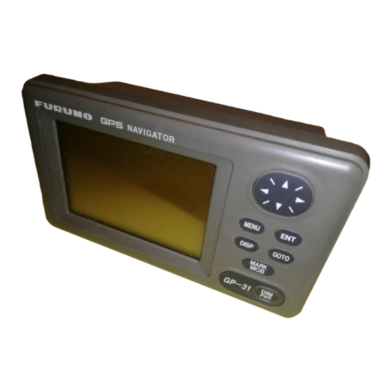
1.1 Control Description Press once: Zoom, centering, or escapes from current opera- tion, depending on display in use. Press twice: Opens menu. Selects display mode. Removing the hard cover To remove the hard cover, squeeze it at its top and bottom right (or left) corners and pull it toward you. -
Page 10: Turning On And Off The Power
1.2 Turning On and Off the Power Turning on the power Press the [DIM/PWR] key. The unit beeps and then starts up with the last-used dis- play mode. Your equipment takes about two minutes to find its position when turned on for the very first time. -
Page 11: Display Modes
1.4 Display Modes Your unit has five display modes: Plotter Display, Highway Display, Steering Display, Nav Data Display and User Display (digital data or speedometer). Press the [DISP] key to select a display mode. Each time the key is pressed, the display mode changes in the sequence shown below. - Page 12 Plotter display The plotter display traces own ship’s track, and shows position, course, speed, and hori- zontal display range setting. Figure 1-4 Plotter display Highway display The highway display provides a 3-D view of own ship’s progress toward destination. Nav data is also shown.
- Page 13 Steering display The steering display provides steering information such as ship’s speed, course; range, bearing, ETA and TTG (Time-To-Go) to destination. Figure 1-6 Steering display Nav data display The nav data display shows position in latitude and longitude (or TDs), course, speed, date and time.
- Page 14 User displays Two user displays are available, digital and speedometer, and the operator may select which to display. The default display is the digital display. Digital display The digital display shows digital navigation data. The user may choose what data to dis- play in the three cells below the receiver status, date and time indications.
-
Page 15: Basic Menu Operation
1.5 Basic Menu Operation Most operations of the your unit are car- ried out through the menu. Below is a quick introduction to how to select a menu and change menu settings. If you get lost in op- eration, press the [MENU] key to return to the MAIN menu. -
Page 16: Simulator Display
5. Press to display “–”. 6. Press to send the cursor to the next digit. 7. Press to display 0. 8. Press to send the cursor to the next digit. 9. Press to display 6. 10.Press to send the cursor to the next digit. - Page 17 13.To turn off the simulator display, select OFF at step 5 in this procedure, press the [ENT] key, and press the [MENU] key twice to finish. Note: If the power is reset while the simu- lator display is in use, the indication SIMU- LATION MODE appears at the top of the screen at the next power up, in addition to the indication SIM.
- Page 18 This page is intentionally left blank.
-
Page 19: Plotter Display Overview
2. PLOTTER DISPLAY OVERVIEW 2.1 Enlarging/Shrinking the Display Range You may increase or decrease the display range on the plotter and highway displays. The horizontal range in the plotter display is available among .02 (40 yd), .05 (101 yd), 0.1 (202 yd), 0.2 (405 yd), 0.5, 1, 2, 5, 10, 20, 40, 80, 160 and 320 nautical miles. -
Page 20: Shifting The Display
Figure 2-4 Data displayed on the plotter display when the cursor is turned off 2.3 Shifting the Display The display can be shifted on the plotter display. Operate the cursor pad to place the cursor at an edge of the screen. The dis- play shifts in the direction opposite to cur- sor pad operation. -
Page 21: Erasing Track
Figure 2-7 Track recording method selection window 5. Select OFF, DISTANCE or AUTO and then press the [ENT] key. OFF: Track is neither recorded or plot- ted. This setting is useful when you do not need to record track, for example, when returning to port. - Page 22 This page is intentionally left blank.
-
Page 23: Waypoints (Marks)
3.1 Entering Waypoints In navigation terminology a waypoint is a particular location on a voyage whether it be a starting, intermediate or destination waypoint. Your unit can store 950 waypoints. Waypoints can be entered on the plotter display four ways: at cursor po- sition, at own ship’s position, through the menu (manual input of L/L or TD), and by MOB position. - Page 24 e) The cursor is on the date/time field. Press the [ENT] key. f) Enter a comment (max. 16 charac- ters) with the cursor pad (the same as you did when entering waypoint name) and press the [ENT] key. To create a space, select “blank” char- acter.
-
Page 25: Entering The Mob Mark
Figure 3-7 Screen for entering waypoint name 6. Enter name (if desired) with the cursor pad and press the [ENT] key. Figure 3-8 Screen for entering waypoint latitude and longitude 7. Use the cursor pad to place the cursor on the second line (latitude or TD) and press the [ENT] key. -
Page 26: Displaying Waypoint Name
Figure 3-11 Screen appearance when MOB is set as destination 3.3 Displaying Waypoint Name You may display on the plotter display all waypoint names or only the GOTO waypoint name as follows: 1. Press the [MENU] key once or twice to display the menu. -
Page 27: Deleting Waypoints
3.5 Deleting Waypoints 1. Press the [MENU] key once or twice to display the menu. 2. Select ERASE and press the [ENT] key. Figure 3-14 ERASE menu 3. The cursor is on the “WAYPOINTS/ MARKS?” field. Press the [ENT] key. Figure 3-15 ERASE WP/MRK display 4. - Page 28 This page is intentionally left blank.
-
Page 29: Routes
In many cases a trip from one place to an- other involves several course changes, re- quiring a series of waypoints which you navigate to, one after another. The se- quence of waypoints leading to the ultimate destination is called a route. Your unit can automatically advance to the next waypoint on a route, so you do not have to change the destination waypoint repeatedly. - Page 30 Figure 4-4 ROUTES menu 8. The LOG field shows the first and last waypoints entered for the log route you are currently creating. Select the LOG field and press the [ENT] key. The EDIT/ MOVE window appears. Figure 4-5 EDIT/MOVE window 9.
- Page 31 Figure 4-9Waypoint data screen 9. Select “Exit?.” 10.Press the [ENT] key to register the route. Then, ROUTES list shows the name of the first and last waypoints, next to route number. Figure 4-10 ROUTES list 11.Press the [MENU] key twice to finish. Creating a route with preregistered waypoints from the waypoint list 1.
-
Page 32: Editing Routes
Creating a track-based route This method stores current position at ap- propriate intervals. It is useful for retracing previous ship’s track. 1. Press the [MARK/MOB] key. Figure 4-15 MOB window 2. Change name, comment, mark shape if desired. Select “LOG RT?” and press the [ENT] key. - Page 33 Note: If the name selected at step 8 has not been used, the window shown in Figure 4-19 appears. Select “CREATE?” or “RENAME?” as appropriate and press the [ENT] key. Figure 4-20 CREATE, RENAME prompt 10.Select “Exit?.” 11.Press the [ENT] key. 12.Press the [MENU] key twice to finish.
-
Page 34: Deleting A Route
1. Press the [MENU] key once or twice to display the menu. 2. Select ROUTES and press the [ENT] key. 3. Select a route from the ROUTES list, and press the [ENT] key. 4. Place the cursor on the waypoint to skip. 5. -
Page 35: Navigation
Destination can be set four ways: by cur- sor, by waypoint, by route, and by MOB po- sition. Previous destination is cancelled whenever a destination is newly set. 5.1 Setting Destination by Cursor 1. Press the [GOTO] key to display the GOTO window. -
Page 36: Setting Route As Destination
4. Select a waypoint. 5. Press the [ENT] key. Own ship’s position becomes starting point and a dashed line runs between it and the waypoint selected, which is shown in re- verse video. 5.3 Setting Route as Destination 1. Press the [GOTO] key. 2. -
Page 37: Alarms
There are seven alarm conditions which generate both aural and visual alarms: Ar- rival alarm, Anchor watch alarm, XTE (Cross-Track Error) alarm, Speed alarm, DGPS alarm, Time alarm, and Trip alarm. When an alarm setting is violated, the buzzer sounds, and the name of the offend- ing alarm and the alarm icon appear on the display. -
Page 38: Xte (Cross Track Error) Alarm
4. If ARV is not selected from the ARV/ANC field, select the ARV/ANC field and press the [ENT] key. The display shown in Fig- ure 6-4 appears. Select ARV and press the [ENT] key. (If ARV is already se- lected, select the ARV/ANC field and press Figure 6-4 Arrival/anchor window 5. -
Page 39: Speed Alarm
6. For ON, press the [ENT] key again. 7. Enter alarm range (range: 0.01-99.99 nm) with the cursor pad. 8. Press the [ENT] key. 9. Press the [MENU] key twice to finish. When own ship strays from the intended track by the range set here, the buzzer sounds and message XTE ERROR! and the alarm icon appear. -
Page 40: Trip Distance Alarm
6.6 Trip Distance Alarm This alarm alerts you by aural and visual alarms when your boat has traveled a greater distance than the preset trip alarm distance. 1. Press the [MENU] key once or twice to open the menu. 2. Select ALARMS. 3. -
Page 41: Other Functions
7.1 Calculating Range, Bearing and TTG Range and bearing between two waypoints 1. Press the [MENU] key once or twice to open the menu. 2. Select CALCULATE. 3. Press the [ENT] key. Figure 7-1 CALCULATION menu 4. Press the [ENT] key to display the win- dow shown in Figure 7-2. -
Page 42: Dgps Setup, Dgps Data
To manually adjust the GP-36’s beacon re- ceiver, or set up the GP-36 or GP-31 to use an external DPGS beacon receiver, do the following: 1. Press the [MENU] key once or twice to open the menu. - Page 43 Note: When connecting a FURUNO external DGPS beacon receiver (such as GR-80) to the GP-31, turn the GR- 80’s remote function on to set up the beacon receiver with data set on the GP-31. 5. The cursor is on the STATION field.
- Page 44 Figure 7-9 STATION (USER) display 6. Select “NEW?” and press the [ENT] key. The following display appears. Figure 7-10 NEW USER CHANNEL display 7. Press the [ENT] key, enter frequency of the station, and press the [ENT] key. 8. Press the [ENT] key, enter baud rate of the station, and press the [ENT] key.
-
Page 45: Bearing Reference
Figure 7-12 Prompt for erasure of all user channels 7. Press the [ENT] key to erase all user channels. Erasing individual user channels 1. Press the [MENU] key twice to open the menu. 2. Select D-GPS and press the [ENT] key. 3. -
Page 46: Geodetic Chart System
5. Select AUTO or MANU and press the [ENT] key. For automatic magnetic variation, current magnetic variation appears to the right of AUTO. 6. If you selected AUTO, no further opera- tion is necessary; press the [MENU] key twice to finish. For MANU, press the [ENT] key and enter magnetic variation as follows: a) If necessary, change coordinate from... -
Page 47: Time Difference (Using Local Time)
3. The cursor is on the first line. Press the [ENT] key. The following window ap- pears. XX.XXX' XX'XX.X" LC TD DE TD Figure 7-12 LAT/LON, LC TD, DE TD selection window 4. Select XX.XXX’, XX’XX.X”, LC TD (Lo- ran C) or DE TD (Decca). XX.XXX’: Shows position with no sec- onds. - Page 48 Selects position fixing method; 2D or 2/3D. 2D requires three satellites in view of the GPS receiver; 2/3D requires three or four satellites in view of the GPS receiver, which- ever is available. When the 2D mode is selected, enter the antenna height above the waterline, to obtain accurate position data.
-
Page 49: User Display Setup
7.10 User Display Setup The user display, which appears when the [DISP] key is pressed several times, may be either digital data (default display) or the speedometer display. Figure 7-14 User displays The user may choose three items of navi- gation data to display on each user display. -
Page 50: Resetting Trip Distance
3. Select WIRING INFO and press the [ENT] key to display the wiring diagram 7-10 Figure 7-20 Connection of GP-36/GP-31 to PC using a DSUB 9-pin connector A DSUB 25-pin (EIA-232) may also be used to make the connection. In this case the wiring diagram is as follows. - Page 51 7. Press any key to escape. Uploading data from a PC PC?. Note that all waypoint and route data stored in GP-36/GP-31 will be deleted when data is uploaded. 1. Press the [MENU] key once or twice to open the menu, select I/O SETUP and press the [ENT] key.
- Page 52 6. Press the [ENT] key. Note: The waypoint and route data are deleted when the [ENT] key is pressed. Figure 7-28 Display when data is being loaded 7. When the loading is completed, the fol- lowing message appears. Figure 7-29 Display when data is loaded successfully 8.
- Page 53 when the number of characters are less than 6.) 6: Waypoint color (This field is always kept NULL.) 7: Waypoint comment (2 byte for mark code + 16 characters of comment.) 1st byte of mark code: Fixed to '@'. 2nd byte of mark code:Internal mark code + 'a' (0 x 61).
-
Page 54: Time Display
7.13 Time Display You may display the time in 12-hour or 24- hour notation, and the default setting is 24- hour notation. AM or PM is shown when 12-hour notation is selected. 1. Press the [MENU] key once or twice to open the menu. -
Page 55: Maintenance And Troubleshooting
8. MAINTENANCE & TROUBLESHOOTING 8.1 Maintenance Check the following points regularly to maintain performance: • Check that connectors on the rear panel are firmly tightened and free of rust. • Check that the ground system is free of rust and the ground wire is tightly fas- tened. -
Page 56: Displaying The Gps Satellite Monitor Display
03 appears as the re- sult when no connector is connected. Note 3: No program number shown for BEACON in case of the GP-31. Note 4: CNT is the number of times test has been consecutively executed. -
Page 57: When "Battery Alarm!" Appears
Note : When it is expected that the GP-31/36 will not be used for a long time, execute the above procedure before turning the power off,to prevent loss of data. -
Page 58: Clearing Data
8.6 Clearing Data You may clear GPS data, menu settings and all backup data to start afresh. 1. Press the [MENU] key once or twice to open the menu. 2. Select ERASE and press the [ENT] key. 3. Select GPS DATA?, MENU SETTINGS, or ALL BACKUP DATA as appropriate and press the [ENT] key. -
Page 59: Installation
The radar beam will obstruct or prevent reception of the GPS signal. • The location should be well away from a VHF/UHF antenna. A GPS receiver is in- terfered by a harmonic wave of a VHF/ UHF antenna. • There should be no interfering object within the line-of-sight to the satellites. -
Page 60: Interconnection Diagram
9.3 Wiring The figure below shows where to connect cables on the rear of the display unit. Please review the WARNING SHEET at the front of this manual before wiring the equipment. ANTENNA UNIT (Shown: GPA-018) GPS ANT DISPLAY UNIT POWER (10.8-31.2 VDC) 1A FUSE... -
Page 61: Initial Settings
9.4 Initial Settings This equipment can output navigation data to external equipment, in NMEA 0183 for- mat. For example, it can output position data to a radar or echo sounder for display on its display screen. Output data format, data sentences NMEA 0183 version 1.5 or 2.0 can be se- lected through the menu. - Page 62 Output setting 1. Press [MENU] once or twice to open the menu. 2. Operate the cursor pad to select I/O SETUP. 3. Press the [ENT] key. I/O SETUP DATA1 NMEA-REM1 DATA2 : NMEA-REM NMEA VER : VER2.0 SAVE WP/RTE LOAD WP/RTE LOAD WP YEOMAN? WIRING INFO?
-
Page 63: Menu Tree
Menu Tree Default settings shown in boldface italic. AP-1... - Page 64 AP-2...
-
Page 65: Loran C Chains
Chain Central Pacific Canadian East Coast Commando Lion (Korea) Canadian West Coast South Saudi Arabia Labrador Sea Eastern Russia Gulf of Alaska Norwegian Sea Southeast USA Mediterranean Sea Western Russia North Central USA North Saudi Arabia Great Lakes South Central USA West Coast USA Northeast USA Northeast Pacific (old) -
Page 66: Decca Chains
Chain Chain Chain code South Baltic Vestlandet Southwest British Northumbrian Holland North British Lofoten North Baltic North West Trondelag English North Bothnian Southern Spanish North Scottish Gulf of Finland Danish Irish Finnmark French South Bothnian Hebridean Frisian Islands Helgeland Location Chain Chain Europe... -
Page 67: Geodetic Chart List
001: WGS84 002: WGS72 003: TOKYO : Mean Value (Japan, Korea & Okinawa) 004: NORTH AMERICAN 1927 : Mean Value (CONUS) 005: EUROPEAN 1950 : Mean Value 006: AUSTRALIAN GEODETIC 1984 : Australia & Tasmania 007: ADINDAN : Mean Value (Ethiopia & Sudan) 008: : Ethiopia 009:... -
Page 68: Specifications
Approx. 50 m (GPS), or approx. 5 m (DGPS), 95% of the time, horizontal dilution of position (HDOP) 4 Note: All GPS receiver are subject to degradation of position and velocity accuracy under the U.S. Department of Defense. Position may be degraded. - Page 69 4. INPUT/OUTPUT DATA (1) Data 1 Output Data: (2) Data 2 Output Data: Input Data: 5. POWER SUPPLY (1) GP-31 (2) GP-36 6. ENVIRONMENTAL CONDITION (1) Ambient Temperature (2) Relative Humidity (3) Water proofing (4) Vibration 7. COATING COLOR (1) Display Unit...
-
Page 78: Index
Alarms anchor watch 6-2 arrival 6-1 DGPS 6-3 speed 6-3 time 6-3 trip 6-4 XTE 6-2 Anchor watch alarm 6-2 Arrival alarm 6-1 Battery replacement (technicians only) 8-3 Bearing reference 7-5 Buzzer type 6-4 Centering own ship's position 2-2 Contrast 1-2 Control description 1-1 Cursor 2-1–2-2 Data clear 8-4... - Page 79 Satellites disabling 7-8 GPS satellite monitor display 8-2 Simulation mode 1-8 Smoothing 7-8 Speed alarm 6-3 Speed averaging 7-8 Speedometer display 1-6 Steering display 1-5 TDs (Loran C or Decca) setup 7-6 Time alarm 6-3 Time difference 7-7 Time display 7-14 Track erasing 2-3 plotting interval 2-2...
Need help?
Do you have a question about the GP-31 and is the answer not in the manual?
Questions and answers