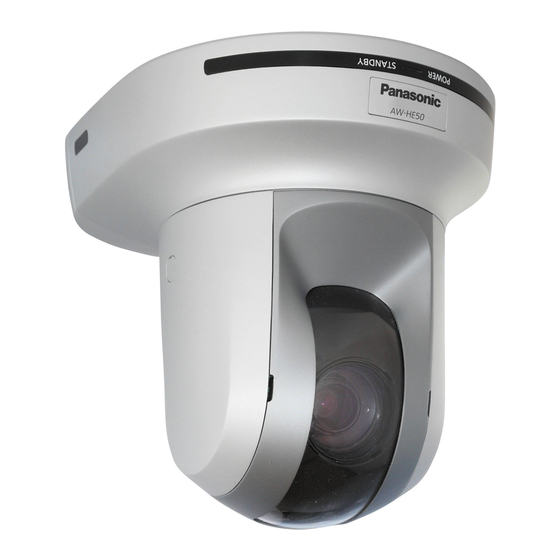
Panasonic AW-HE50HN Operating Instructions Manual
Hd integrated camera
Hide thumbs
Also See for AW-HE50HN:
- Additional instructions (1 page) ,
- Operating instructions manual (90 pages)
Table of Contents
Advertisement
Before operating this product, please read the instructions carefully and save this manual for future use.
For instructions on how to operate this HD Integrated Camera and how
to establish its settings, refer to the "Operations and Settings" manual
(PDF file) which can be found on the CD-ROM supplied with the camera.
Operating Instructions
Model No.
Installation Instructions provided
HD Integrated Camera
AW‑HE50HN
AW‑HE50SN
<Basics>
3TR006490BAA
Advertisement
Table of Contents

Related Manuals for Panasonic AW-HE50HN


Summary of Contents for Panasonic AW-HE50HN
-
Page 1: Operating Instructions
Operating Instructions <Basics> Installation Instructions provided HD Integrated Camera AW‑HE50HN Model No. AW‑HE50SN Before operating this product, please read the instructions carefully and save this manual for future use. For instructions on how to operate this HD Integrated Camera and how to establish its settings, refer to the “Operations and Settings”... -
Page 2: Safety Precautions
Safety precautions WARNING: CAUTION TO PREVENT INJURY, THIS APPARATUS RISK OF ELECTRIC SHOCK DO NOT OPEN MUST BE SECURELY ATTACHED TO THE FLOOR/WALL IN ACCORDANCE WITH THE CAUTION: TO REDUCE THE RISK OF ELECTRIC SHOCK, INSTALLATION INSTRUCTIONS. DO NOT REMOVE COVER (OR BACK). NO USER SERVICEABLE PARTS INSIDE. -
Page 3: Important Safety Instructions
Safety precautions IMPORTANT SAFETY INSTRUCTIONS Read these operating instructions carefully before using the unit. Follow the safety instructions on the unit and the applicable safety instructions listed below. Keep these operating instructions handy for future reference. 1) Read these instructions. 10) Protect the power cord form being walked on or pinched particularly... -
Page 4: Table Of Contents
Contents Safety precautions ............2 How to install and connect the unit ......20 When using the WV‑Q105 (optional accessory) ..24 Before use ................. 5 Overview ................ 5 Changing the direction of the nameplate ..... 25 Concerning the Operating Instructions ......5 Removing the camera ............ -
Page 5: Before Use
Before use Overview Concerning the Operating Instructions p p This unit is a compact full HD camera integrated with a pan‑tilt head and featuring a newly developed 1/3‑inch full p p For the purposes of this manual, the model number HD MOS sensor and digital signal processor (DSP). -
Page 6: Required Personal Computer Environment
Before use Required personal computer IMPORTANT environment p p Failure to provide the required personal computer environment may slow down the delineation of the images on the screen, make it impossible for Intel ® Core 2 DUO 2.4 GHz or faster the web browser to work and cause other kinds of recommended problems. -
Page 7: Disclaimer Of Warranty
Before use Disclaimer of warranty Network security IN NO EVENT SHALL Panasonic System Networks Co., Ltd. As you will use this unit connected to a network, your BE LIABLE TO ANY PARTY OR ANY PERSON, EXCEPT attention is called to the following security risks. -
Page 8: Characteristics
The unit can also be used together with the cameras and pan‑tilt head unit systems currently available from Panasonic System Networks Co., Ltd. so that an existing system can be used to advantage to put together a system that is even more flexible. -
Page 9: Controller Supported
Controller supported p p AW-RP655 Notes p p AW-RP555 When connecting the AW-RP655 p p AW-RP50 p p The camera menus that are operated using the LCD panel on the AW‑RP655 cannot be used. pp It may be necessary to upgrade the version of the ... -
Page 10: Installation Precautions
Installation precautions In addition to heeding the points presented in the “Safety precautions”, observe the following precautions as well. Concerning the installation location Ensure that the installation work complies with the Install the unit in a stable location which will not be technical standards governing electrical equipment. - Page 11 Installation precautions Be absolutely sure to use the bracket and screws Connecting the power cable supplied when installing the unit. Be absolutely sure to connect the power cable of the AC adapter through a circuit breaker using one of the p p Do not mount the unit by employing any methods other than those specified.
-
Page 12: Operating Precautions
Operating precautions Zooming and focusing Shoot under the proper lighting conditions. To produce pictures with eye‑pleasing colors, shoot under When the focus is set manually, out‑of‑focusing may occur the proper lighting conditions. during zooming. The pictures may not appear with their proper colors when After zooming, if necessary, either adjust the focus or set the focus to auto. - Page 13 Operating precautions Turn off the power before connecting or disconnecting Maintenance the cables. Turn off the unit’s power before proceeding with Always be sure to turn off the power before connecting or maintenance. disconnecting the cables. Otherwise, you may injure yourself. Wipe the surfaces using a soft dry cloth.
-
Page 14: Concerning The Wireless Remote Control (Optional Accessory)
Concerning the wireless remote control (optional accessory) This unit can be operated by remote control using a wireless remote control (model number: AW-RM50G) purchased separately. Check out the following points before using the wireless remote control. Consult your dealer concerning the purchase of a wireless remote control. -
Page 15: Parts And Their Functions
Parts and their functions Camera unit 1 Mount bracket for installation surface (supplied accessory) Mount this bracket onto the installation surface, and then attach the camera main unit to the bracket. 2 Drop-prevention wire Pull out the wire from the bottom panel of the camera main unit, and attach it to the hook of the mount bracket. - Page 16 Parts and their functions 9 LAN connector for IP control [LAN ACT/LINK] IR ID switches [IRID] This LAN connector (RJ45) is connected when exercising [CAM1] [CAM2] [CAM3] [CAM4] IP control over the unit from an external device. Use a cable with the following specifications for the connection to the LAN connector: When connecting through a hub: LAN cable* (category 5 or above, straight cable),...
-
Page 17: Wireless Remote Control (Optional Accessory)
Parts and their functions Wireless remote control 3 MENU button Each time this is pressed for 2 seconds, operation (optional accessory) switches between displaying the unit’s menu and exiting the menu. When it is pressed quickly (for less than 2 seconds) while a menu is displayed, the setting change is canceled. - Page 18 Parts and their functions 9 PRESET/LIMIT button A/FOCUS button This is used to register the settings in the preset This is used when automatically adjusting the lens focus. memories or set or release the limiters. M/FOCUS button When a preset memory call button is pressed while the PRESET/LIMIT button is held down, the information on This is used when manually adjusting the lens focus.
-
Page 19: Setting The Remote Control Ids
Setting the remote control IDs The wireless remote control (optional accessory) is capable of operating up to four units. IDs are used to set which units are selected when the [CAM1], [CAM2], [CAM3] and [CAM4] buttons on the wireless remote control have been pressed. p p When using a multiple number of units, set a different remote control ID for each unit. -
Page 20: How To Install And Connect The Unit
How to install and connect the unit Be absolutely sure to read through the “Installation precautions” on pages 10 to 11. The procedure given here is for the kind of installation where the unit is suspended from an overhead surface, but the same steps are followed for a stand‑alone installation. - Page 21 How to install and connect the unit Mount the mount bracket onto the installation surface. p p Use the bracket mounting screws (M4, bind‑head: 10 mm long) supplied with the unit. p p For proper clamping torque, securely attach the screws using the specified tools. Screw diameter Clamping torque 1.47 N ·...
- Page 22 How to install and connect the unit Mount the unit. p p Align the position of the hole for checking the positioning with the status display lamp. p p Align the holes on the camera main unit used to insert the bottom panel with the protrusions on the mount bracket used for inserting the camera, push the bracket and camera firmly together, and rotate the main unit by about 15 degrees in the direction of the arrow.
- Page 23 How to install and connect the unit Connect the rear panel connectors. Anchor the AC adapter cable in place using the cable clamp. [AW-HE50H] Square hole (one at either side) Cable clamp LAN cable Video output cable Interface cable AC adapter cable Screw for cable cover (M3 screw) Tab (one at either side) (with flat washer, spring washer)
-
Page 24: When Using The Wv-Q105 (Optional Accessory)
How to install and connect the unit When using the WV-Q105 (optional accessory) It is recommended that you provide an inspection opening or other such space for access purposes in the area near where the equipment is installed in order to facilitate installation and the wiring connections work. Before mounting the mount bracket, check that the installation location is strong enough to withstand the total mass (approx. -
Page 25: Changing The Direction Of The Nameplate
Changing the direction of the nameplate When the unit is mounted on the ceiling, its nameplate will be upside down. The direction of the unit’s nameplate can be changed. Push in the part indicated by the arrow, and pull out the nameplate. Change the direction of the nameplate. -
Page 26: Removing The Camera
Removing the camera Turn off the circuit breaker and power. Remove the cable cover. p p Remove the screw (M3) for the cable cover used to secure the cover. p p Push the tab parts of the cover to disengage the cover. Disconnect the cables. -
Page 27: Stand-Alone Installation (When The Mount Bracket Is Going To Be Used)
Stand-alone installation (when the mount bracket is going to be used) The same steps are followed as for the kind of installation where the unit is suspended from an overhead surface (pages 20 to 23). Check the mounting space. Note p p As with installing the unit suspended from an overhead surface, carefully check the space where the unit will be mounted, and then decide if it is appropriate to install the unit in that space. - Page 28 Stand-alone installation (when the mount bracket is going to be used) Check the mounting. Connect the rear panel connectors. [AW-HE50H] Cable clamp Screw for cable cover (M3 screw) (with flat washer, spring washer) AC adapter cable Square hole (one at either side) Interface cable Video output cable Tab (one at either side)
-
Page 29: Stand-Alone Installation (When The Mount Bracket Is Not Going To Be Used)
Stand-alone installation (when the mount bracket is not going to be used) When installing the unit on a desktop Place the unit flat on the surface. Notes p p Install the unit in a stable location which will not be susceptible to shaking. If the unit is installed in a location which is susceptible to shaking, this will cause the unit’s images to shake in turn. -
Page 30: Connections
Connections Connections with an HD monitor HD Integrated Camera AW-HE50 HDMI signal (AW-HE50H only), SDI signal (AW-HE50S only) or HD analog component signal HD monitor Wireless remote control (optional accessory) Up to four units can be operated using one remote control. -
Page 31: Connections With A Controller (Aw-Rp655 Or Aw-Rp555)
Connections Connections with a controller (AW-RP655 or AW-RP555) LAN cable (straight cable) Pan-tilt head/ camera control signals HD Integrated Camera AW-HE50 Multi Hybrid HDMI/SDI video signal Control Panel AW-RP555 AC Adapter AW-PS510A Monitor RJ-45 relay Accessory AC adapter Multi-Interface adapter Cable AW-CA20T6... -
Page 32: System Example 1
Connections System example 1 HD Integrated Camera HD Integrated Camera* AW-HE50S AW-HE50S Accessory AC adapter Genlock signal generator Pan-tilt head and camera control signal SDI video signal Monitor 1 Monitor 2 Monitor Monitor Switcher System TALLY Multi-Function Controller AW-RP655 AC Adapter AW-PS510A *: The AC adapter provided with the unit is... -
Page 33: System Example 2
Connections System example 2 HD Integrated Camera HD Integrated Camera* AW-HE50S AW-HE50S Accessory AC adapter Genlock signal generator LAN cable SDI video signal (straight cable) Monitor 2 Switching hub Monitor 1 LAN cable (straight cable) Monitor Monitor Compact Live Switcher AW-HS50 Remote Camera Controller AW-RP50... -
Page 34: Network Settings
Network settings Installing the software Use the Easy IP Setup Software to establish the unit’s settings Be absolutely sure to read through the “Readme.txt” on the CD‑ROM supplied with the unit first before attempting to The settings related to the unit’s network can be established install the software. - Page 35 Network settings Start the Easy IP Setup Software. Click the MAC address/IP address of the p p After the [Apply] button is clicked, it takes about camera to be set, and click the [IP setting] 2 minutes for the settings in the unit to be completed. If the AC adapter or LAN cable is disconnected button.
-
Page 36: Troubleshooting
Troubleshooting q Operation Reference Symptom Cause and remedial action pages p p Is the AC adapter securely connected to the AC outlet? ––– p p If the power plug of the AC adapter connected properly? ––– p p If the unit is connected to the controller, has it been connected No power properly? P.31 to 33... - Page 37 Troubleshooting Reference Symptom Cause and remedial action pages Do not attempt to adjust the slowest speed at which the camera is to start panning and tilting since this adjustment does not need to be undertaken when the unit is connected with the AW-HE50. If an attempt is made to undertake this adjustment, the following will occur: The adjustment of...
- Page 38 Troubleshooting Reference Symptom Cause and remedial action pages p p Has the same IP address setting been used for another device? Is there a lack of consistency between the address set and the network subnet at the installation destination? [When the personal computer is connected to the unit within the same subnet] Have the IP addresses of the unit and personal computer been –––...
- Page 39 Troubleshooting q Video Reference Symptom Cause and remedial action pages p p Has the unit been connected properly to the other connected P.30 to 33 devices? p p If the system is configured in such a way that the picture is also <Operations and No pictures are switched when the unit to be operated is selected, has the correct...
- Page 40 Troubleshooting Reference Symptom Cause and remedial action pages p p These are caused by the reflections of the light between the lens Ring-shaped and the cover in front of the lens. Find a way of optimizing the reflections appear position of the lighting relative to the position of the unit, and –––...
-
Page 41: Web Settings
Troubleshooting q Web settings Depending on the OS installed on the PC, the following may occur. Follow the instructions below when the following has occurred. By performing the following solutions, other applications and the security level may not be affected. The “Information bar”... -
Page 42: Appearance
Appearance Unit: mm (inch) 160 (6-5/16) 85 (3-11/32) AW-HE50H 80 (3-5/32) 72 (2-13/16) 166 (6-9/16) AW-HE50S... -
Page 43: Specifications
Specifications Power requirements: DC 12 V 10 % (AC adapter provided) Power consumption: DC 12 V, 1.2 A (AW‑HE50H) DC 12 V, 1.3 A (AW‑HE50S) indicates safety information. GENERAL INPUT Ambient operating temperature: Input connector: DC 12 V IN, 0 °C to +40 °C (32 °F to +104 °F) EXT SYNC IN (BNC) (AW‑HE50S only) -
Page 44: Optional Accessories
Specifications FUNCTIONS AND PERFORMANCE Camera/pan-tilt head control: [Camera unit] IP connecting When connecting through a hub: cable LAN cable* (category 5 or above, Imaging sensors: 1/3˝ Full‑HD MOS straight cable), max. 100 m (328 ft.) Lens: Motorized 18 zoom, f/1.6 to 2.8 When a hub is not used: (f=4.7 to 84.6 mm;... - Page 45 Memo...
- Page 46 Panasonic Latin America, S.A. P.O.Box 0816‑03164 Panama, Republic of Panama Tel: +507‑229‑2955 Fax: 507‑229‑5352 Panasonic do Brasil Ltda. Rua Cubatão, 320‑8 andar‑Paraíso CEP 04013‑001‑ São Paulo ‑ SP Tel: (11)3889‑4000 Fax: (11)3889‑4107 © Panasonic System Networks Co., Ltd. 2010 Printed in Japan F0410S1050...
Need help?
Do you have a question about the AW-HE50HN and is the answer not in the manual?
Questions and answers