
Related Manuals for Furman HDS-16

Summary of Contents for Furman HDS-16
- Page 1 HDS-16 HDS-16/HRM-16 HEADPHONE DISTRIBUTION SYSTEM HRM-16 HEADPHONE/AUDIO DISTRIBUTION AND REMOTE MIXING SYSTEM MONITORING SERIES...
- Page 2 HRM-16 via a 50-pin Centron- ics cable. This cable also transports the DC power to each HRM-16 so they do not require a power cable or “wall wart.” Each HDS-16 has six Centronics outputs on the rear panel, and additional HRM-16’s can be daisy-chained together.
-
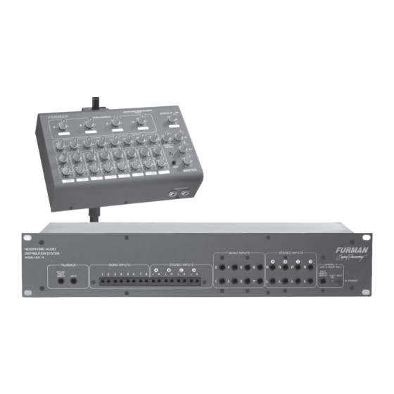
Page 3: Front Panel
The front panel is shown above; the TT and ¼-inch input sections are shown in detail in Figure 2 and Figure 4, respectively. Note: Although the POWER indicator LED is located on the far right of the HDS-16 front panel, the AC power ON/OFF switch is on the rear panel. normally located near the main mixing console, provides the power and signal conditioning for a maximum of eight HRM-16’s. -
Page 4: Studio Mode
HRM-16’s TALKBACK VOLUME control. Figure 2: Detail of HDS-16 front panel: Talkback and TT inputs Figure 2: Detail of HDS-16 front panel: Talkback and TT inputs There are two talkback modes designed for... - Page 5 HDS-16/HRM-16 HEADPHONE DISTRIBUTION SYSTEM Figure 3: Changing the talkback mode inside the HDS-16...
- Page 6 HDS-16/HRM-16 HEADPHONE DISTRIBUTION SYSTEM CHANGING THE TALKBACK MODE A jumper located inside the HDS-16 selects between two talkback modes. 1. Use a a Phillips screwdriver to unscrew the middle two screws located near the top of the front panel and all screws on the top.
-
Page 7: Rear Panel
SOLO function, both must be in the off position to deactivate it. REAR PANEL The HDS-16 rear panel has six, 50-pin, Cen- tronics output connectors for the HRM-16s, AC-power, and ground switches (Figure 5). While male-to-male Centronics cables are... -
Page 8: Top Panel
HRM-16s are connected in series from a single HDS-16 output. Parallel: Each HRM-16 is connected directly to ■ the HDS-16 in a star con fi g u ra tion. Series: One HRM-16 is connected directly to ■ the HDS-16 with additional HRM-16’s con- nect ed together in a daisy chain. - Page 9 Restore normal operation by removing the defective cable or HRM-16 and turn off the power to the HDS-16 for at least 30 seconds. The AC-line fuse is a 1-Amp Slo-Blo. Replace it only with a fuse of the same type and rating.
-
Page 10: Three-Year Limited Warranty
HDS-16/HRM-16 HEADPHONE DISTRIBUTION SYSTEM THREE YEAR LIMITED WARRANTY Furman Sound, Inc., having its principal place of business at 1997 South McDowell Blvd., Petaluma, CA 94954 (“Manufacturer”) warrants its HDS-16/HR-16 (the “Product”) as follows: Manufacturer warrants to the original Pur- chaser of the Product that the Product sold... - Page 11 < 0.002% THD+Noise, 20 Hz - 20 kHz at full rated power DYNAMIC RANGE > 105 dB FREQUENCY RESPONSE +0/-1 dB 13 Hz - 32 kHz POWER REQUIREMENTS HDS-16: 120 VAC, 60 Hz, 82 W; HDS-16E: 230 VAC, 50 Hz, 82 W CROSSTALK < -95 dB at 10 kHz...
- Page 12 Furman Sound, Inc. 1997 South McDowell Blvd. Petaluma, California 94954-6919 USA Phone: 707-763-1010 Fax: 707-763-1310 Web: www.furmansound.com E-mail: info@furmansound.com Made in China 0014 960138-2743 B...
Need help?
Do you have a question about the HDS-16 and is the answer not in the manual?
Questions and answers