Table of Contents
Advertisement
Advertisement
Table of Contents

Related Manuals for Fusion FM-402


Summary of Contents for Fusion FM-402
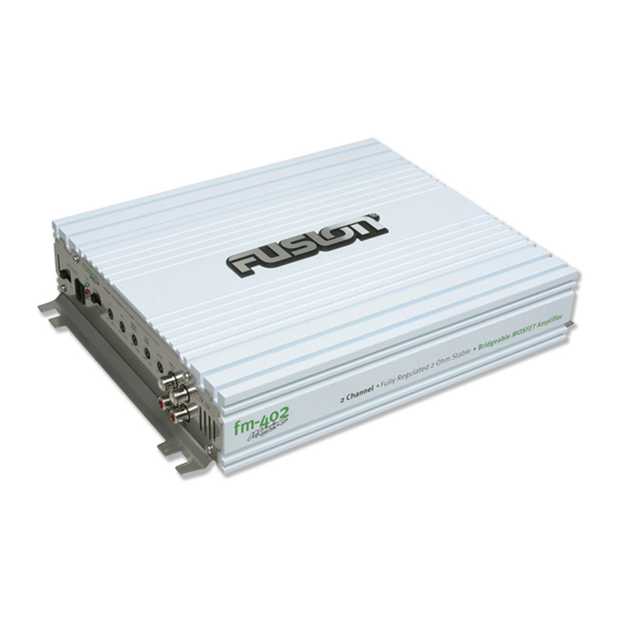
- Page 1 User / Installation Manual Marine Amplifier FM-402...
- Page 2 3 Channel Installation / Power Cable Calculator . . . . . . . . . . . . . . . Pg 9 What sets FUSION apart? 4 Channel Installation / Specifications .
- Page 3 2 Bass Remote Connector damage could result. This port allows connections to the (optional) FP-BASS control. 14 Remote Connection: 3 Power And Status LEDs: This input is for turning the amplifier on and off. This requires a switched positive (+12V) to power ‘ON’ the amplifier, this can be found on the rear of the head unit in the form of an electric antenna output, or a remote this shows if the amplifier has been correctly powered up and if any faults are present. on output. If not available you can wire to the ACC position on the key. 4 Crossover Selector: 15 Fuses: Set the appropriate mode of operation. The 3 positions available are OFF, LP and HP. See points 5 and 6 below. Please ensure the correct type of fuse is fitted, as specified in this manual. PLEASE NOTE: the FM-402 has 1x 5 Low Pass: 25A fuses. Set the crossover switch 2 to LP when a subwoofer is connected. Ensure the crossover frequency is set at 16 Speaker Output: 100Hz or below, this feature is designed to filter all mid to high frequencies that only FULL RANGE speakers should produce. NOTE: Failure to do so could result in speaker damage. See 2/1 channel installation diagrams in this manual for correct speaker connection. 6 High Pass:...
- Page 4 Speaker Wiring amplifier. Choose the correct speaker wire for your application. Most application will require a minimum of 16 gauge. Route these using the If you decide to connect the amplifier yourself, it is important that you read this manual carefully and throughout before start- same precautions as you did when you ran the power cables. Terminate these wires at the speaker end using insulated speaker ing. Once you have finished reading and you still have questions regarding installation, we recommend your FUSION dealer. terminals (not supplied) or by soldering the connection. Make sure the speaker connections are positive to positive and negative to negative. At the amplifier end, use a #2 Phillips screwdriver to loosen the speaker terminals on the amplifier. Connect the Connection speaker wires and tighten the screws securely. Check to make sure you’ve maintained proper polarity and balance. Inputs & Gain Setup FUSION amplifiers are designed to work within a 10 to 16 volt DC range. Before any wires are connected, the vessel’ s electrical system should be checked for correct voltage supply with the help of a voltmeter. First, check the voltage at the battery with the ignition in the OFF position. The voltmeter should read between 12 and 13.8 Volts. If your vehicle’ s electrical system is not up to Low Level Inputs these specification, we recommend having it checked by an auto electrician before any further installation. Once the vessel is checked, make certain the correct cable size is used. We recommend using the following cables calculator diagram on page 8 to Be extra careful with your RCA interconnects. Hiss, engine noise, and fan noise can easily be picked up through RCA cables if run calculate the correct power cable for your application. incorrectly. Avoid running your RCAs near large wire looms and electric fans if possible. Run your RCA cables on the opposite side of the power cable. Be sure to check for correct balance (Red is right and black or white is left) Power Level Control FUSION amplifiers should be wired directly to the battery using the appropriate sized cable. Start at the vehicle battery and run the power cable through to the amplifier. FUSION recommends the use of grommets when passing the power cable through any On the amplifier, is the LEVEL control, this control allows you to match the input level of the amplifier to the output level of your metal wall to avoid sharp corners or sharp body parts that may easily cut through the insulation on the cable.
- Page 5 1 Channel Installation 2 Channel Installation FUSE FUSE PLEASE NOTE: The crossover selector positions PLEASE NOTE: The crossover selector positions Power Cable Calclator Trouble Shooting Total Amperage 0-4ft 4-7ft 7-10ft 10-13ft 13-16ft 16-19ft 19-22ft 22-28ft 0-20 Problem Cause Solution 20-35 Replace with correct fuse. Typically twice the rating of the fuse that Fuse at battery blown or not installed 35-50 is on the amplifier...
-
Page 6: Specifications
Specifications 12.6 Volt power output specification Bandwidth 10Hz - 40kHz Signal to Noise >95dB 50 Watts RMS x 2 @ 4Ω 1% THD+N Separation >60dB 96 Watts RMS x 2 @ 2Ω 1% THD+N Input Sensitivity 300mV - 8V 160 Watts RMS x 1 @ 4Ω Bridged 1% THD+N LP Variable Crossover 40Hz - 160Hz @ 12dB/octave 14.4 Volt power output specification HP Variable Crossover 40Hz - 600Hz @ 12dB/octave 65 Watts RMS x 2 @ 4Ω 1% THD+N Variable Bass Boost 0 - + 18dB @ 45Hz 100 Watts RMS x 2 @ 2Ω 1% THD+N Variable Subsonic Filter 20Hz - 55Hz @ 18dB/octave 200 Watts RMS x 1 @ 4Ω Bridged 1% THD+N Input Impedance 20KW Damping factor >200 T.H.D 0.05% Fuse Ratings 1 x 25A Dimensions(mm) 220 (W) x 260(L) x 57.5(H) - Page 7 Specifications and design are subject to change without notice.
Need help?
Do you have a question about the FM-402 and is the answer not in the manual?
Questions and answers