Table of Contents
Advertisement
Quick Links
Advertisement
Table of Contents

Subscribe to Our Youtube Channel
Related Manuals for Conair Basic 32 Loader Control B32

Summary of Contents for Conair Basic 32 Loader Control B32
- Page 1 Basic 32 Loader Control B32 Model Installation Operation Maintenance Troubleshooting The Conair Group, Inc. Instant Access One Conair Drive Parts and Service Pittsburgh, PA 15202 (800) 458-1960 Phone: (412) 312-6000 (814) 437-6861 Fax: (412)-312-6001 www.conairnet.com UGC007/0702...
- Page 2 User Guide or for incidental, consequential damages in connection with the furnishing, performance or use of this infor- mation. Conair makes no warranty of any kind with regard to this information, including, but not limited to the implied warranties of merchantability and fitness for a particular purpose.
-
Page 3: Table Of Contents
.........1-1 NTRODUCTION ABLE OF Purpose of the User Guide.............1-2 ONTENTS How the Guide is Organized ..........1-2 Your Responsibility as a User ..........1-2 ATTENTION: Read this so no one gets hurt ......1-3 ....2-1 ESCRIPTION What is the B32? . - Page 4 ....6-1 ROUBLESHOOTING ABLE OF Before Beginning ....... .6-2 ONTENTS A Few Words of Caution .
-
Page 5: Introduction
NTRODUCTION Purpose of the User Guide ..1-2 How the guide is organized ..1-2 Your responsibilities as a user ...1-2 ATTENTION: Read this so no one gets hurt .....1-3 UGC007/0702 Basic 32 Loader Control... -
Page 6: Purpose Of The User Guide
This User Guide describes the Conair Basic 32 Loader URPOSE OF Control and explains step-by-step how to install, operate, maintain and repair this equipment. Before installing this product, please take a few moments to UIDE read the User Guide and review the diagrams and safety infor- mation in the instruction packet. -
Page 7: No One Gets Hurt
We design equipment with the user’s safety in mind. You can ATTENTION: avoid the potential hazards identified on this machine by fol- lowing the procedures outlined below and elsewhere in the EAD THIS SO NO User Guide. ONE GETS HURT WARNING: Improper installation, oper- ation or servicing may result in equip- ment damage or personal injury. -
Page 9: Description
ESCRIPTION l What is the B32? ... .2-2 l Typical Applications ..2-2 l How it Works ....2-3 l Specifications . -
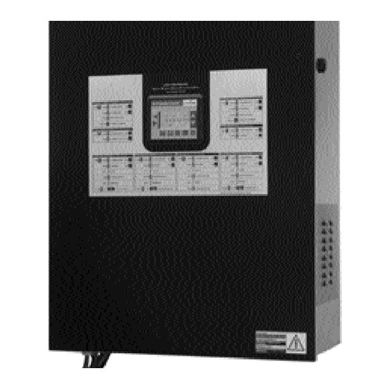
Page 10: What Is The B32
The control is mounted on the front of the I/O station. Inside HAT IS THE is a processor with base, containing up to 8 input/output mod- B32? ules. The number of input and output modules will vary with the number of vacuum receivers and conveying options. Pump Pump System 5... -
Page 11: How It Works
The B32 communicates with each pump, vacuum receiver and OW IT ORKS material valve wired to Input/Output modules within the con- trol enclosure. The B32 controls conveying operation based on settings the operator enters on the HMI. When receivers in a pump system demand material, the B32 turns on the vacuum pump and dust collector in the appropri- ate pump system. -
Page 12: Specifications
B32 loader control cable: 18 gauge shielded, 8-conductor may be used for standard vacuum receivers with up to one optional output and input, otherwise 10-conductor cable is required. Specifications can change without notice. Check with your Conair representative for the most current information. APPLICATION NOTES: Conair vacuum receivers come equipped with a quick-disconnect connec- tor set that includes 10 feet of cable. -
Page 13: Installation
NSTALLATION l Unpacking the Boxes ...3-2 l Preparing for Installation ..3-3 l Installing the B32 ....3-4 l Wiring Considerations . -
Page 14: Unpacking The Boxes
The B32 central loading control comes in one box. The box NPACKING should include: OXES Carefully remove the B32 components from their shipping containers, and set upright. Remove all packing material, protective paper, tape and plastic. Carefully inspect all components to make sure no damage occurred during shipping. -
Page 15: Preparing For Installation
You should plan the location of the B32 control to ensure easy REPARING FOR access and minimal wiring. NSTALLATION Select a mounting location for the control. The interface and Input/Output enclosure can be mounted on a wall or other stable vertical surface. Select a location that: r Is central to loaders that the B32 will control. -
Page 16: Installing The B32
Installation of the B32 control consists of: NSTALLING r Mounting the enclosure. r Wiring loaders to the control. r Wiring pumps to the control. r Wiring material valves to the control. r Connecting the control to a main power source. r Initial setup of the system control. -
Page 17: Mounting The Control
WARNING: Improper installation may result in equipment damage or personal injury. Always maintain a safe ground. Follow the safe grounding procedures in the wiring diagram pack- age. Ground the shielded cable inside the Input/Output enclosure only. Do not operate the equipment at power levels other than those specified on the the equipment data plate. -
Page 18: Connecting To The B32
ONNECTING TO WARNING: Improper installation may result in equipment damage or personal injury. Always refer to the wiring diagrams that came with your controls before making electrical con- nections. The diagrams show the most accurate electrical component information. Use shielded cable unless you run wires in metal conduit. -
Page 19: Wiring Loaders To The B32
The loader wires connect to power terminals or terminals on IRING OADERS the I/O modules inside the control enclosure. The number of loaders and options in the conveying system will determine TO THE the number of connections that are required. Refer to the electrical prints included with this manual for all IMPORTANT: Always refer electrical connections to the loader control. -
Page 20: Connecting Main Power To The B32
The B32 Input/Output enclosure is equipped with a three- ONNECTING prong plug and power cord. Each optional remote touchscreen panel also has its own plug and power cord. OWER Plug the power cord(s) into a grounded 115 TO THE VAC outlet rated for at least 15 Amp service. Make sure the control enclosure is grounded. -
Page 21: Initial Setup
Before you can begin conveying, you must configure and NITIAL ETUP identify the loaders and conveying features you want to use. Procedures on the following pages will explain how to: r Set loader parameters r Enable pumps and loaders r Select security password To begin Initial Setup: Turn on power to the B32. -
Page 22: Setting Loader Parameters
CAUTION: Incorrect configurations will ETTING cause the B32 control to stop. OADER Before enabling loaders and loading functions, make sure the loader, valve or option has been ARAMETERS installed in the system. Each loader and feature must be wired to a correctly installed and enabled input or output module. -
Page 23: Enabling Loaders
To enable the loaders from the main screen: NABLING Use the Up/Down arrows to scroll to OADERS Loader Settings. Press the Enter arrow. The Loader Settings screen displays. Use the up/down arrows to scroll to Loader Enable. Press the Enter arrow. The Loader Enable screen displays. -
Page 24: Selecting A Password
The B32 provides password security to prevent unauthorized ELECTING A changes to loader or system settings. ASSWORD Use the Up/Down arrows to scroll to System Config. Entering the System Configuration screen requires a Supervisor 2 password. Enter the password. To enter the password use the up/down arrows to scroll through the alphanumeric list. -
Page 25: Operation
PERATION l B32 Control Features ...4-2 l Viewing Loader Status ..4-3 l Enabling and Disabling Loaders .....4-4 l Enabling and Disabling Pumps . -
Page 26: B32 Control Features
The B32 operator interface allows you to view the status of the vacu- um receivers and pumps in your conveying system at a glance. It also provides access to screens to enter settings for each loading sta- ONTROL tion, view alarms and change system parameters. EATURES Quick-reference guides Scroll to:... -
Page 27: Viewing Loader Status
To view loader status from the main screen: IEWING Use the Up/Down arrows to scroll to OADER Loader Settings. TATUS Press the Enter arrow. The Loader Settings screen displays. Use the up/down arrows to scroll to Loader 1-16. Press the Enter arrow. The Loader Status screen displays. -
Page 28: Enabling And Disabling Loaders
WARNING: Develop and follow procedures NABLING for safe operation of the system to avoid pos- sible injury or equipment damage. ISABLING The B32 allows operators and maintenance OADERS personnel to disable and enable conveying system components from remote locations. Unexpected energization of these components could result in equipment damage or injury. -
Page 29: Enabling And Disabling Pumps
WARNING: Develop and follow procedures NABLING for safe operation of the system to avoid pos- sible injury or equipment damage. ISABLING The B32 allows operators and maintenance UMPS personnel to disable and enable conveying system components from remote locations. Unexpected energization of these components could result in equipment damage or injury. -
Page 30: Configuring Loaders
You may need to change loader settings whenever you change ONFIGURING materials or to obtain the best conveying performance. OADERS To configure loaders from the main screen: Use the Up/Down arrows to scroll to Loader Config. Press the Enter arrow. The Loader Configuration screen displays. -
Page 31: Assigning Pumps And Loaders
You may need to change loader and pump assignments to SSIGNING match the conveying system vacuum and XXXX OADERS AND To assign loaders and pumps from the main screen: UMPS Use the Up/Down arrows to scroll to Loader Config. Press the Enter arrow. The Loader Configuration screen displays. -
Page 32: Assigning A Backup Pump
A backup pump can be assigned to replace any of the eight SSIGNING A pump systems during operation. ACKUP To assign a backup pump: Use the Up/Down arrows to scroll to Loader Config. Press the Enter arrow. The Loader Configuration screen displays. Use the up/down arrows to scroll to VP Back-Up Select. -
Page 33: Configuring The Alarm
Te loader can be configured for demand alarm, fill alarm or no ONFIGURING alarm. LARM To configure the alarm from the main screen: Use the Up/Down arrows to scroll to Loader Config. Press the Enter arrow. The Loader Configuration screen displays. Use the up/down arrows to scroll to Alarms. -
Page 34: Backing Up The Plc Program
To back up the PLC program and save the configuration: ACKING Use the Up/Down arrows to scroll to PLC P ROGRAM Loader Config. OPTIONAL Press the Enter arrow. The Loader Configuration screen displays. Use the up/down arrows to scroll to Save Config. Press the Enter arrow. -
Page 35: Maintenance
AINTENANCE l Maintenance checklist ..5-2 UGC007/0702 Basic 32 Loader Control... -
Page 36: Preventive Maintenance Checklist
You should develop a preventive maintenance schedule for all REVENTIVE components in the conveying system to ensure optimum operation and performance. AINTENANCE The B32 may require the following maintenance checks: HECKLIST l Whenever you change materials r Verify the loader settings for pump systems or loaders effected by the material change. -
Page 37: Troubleshooting
ROUBLESHOOTING l Before Beginning ... .6-2 l A Few Words of Caution ..6-2 l Identifying the Cause of a Problem ....6-3 l Clearing Interface Alarms . -
Page 38: Before Beginning
Before you begin troubleshooting: EFORE o Find the manuals and wiring diagrams that were shipped with your equipment. EGINNING These materials contain details you will need to diagnose and repair problems in specific components, including custom wiring, features or I/O options not covered in this User Guide. ORDS WARNING: Improper installation, opera- tion or servicing may result in equip-... -
Page 39: Identifying The Cause Of A Problem
The T section explains how to clear an ROUBLESHOOTING DENTIFYING THE alarm, and provides diagnostic tables to help you determine the cause of the alarm. AUSE OF A Diagnostic tables have been divided into: ROBLEM r Conveying System Alarms. These tables focus on the “No Material” and “Pump Overload”... -
Page 40: Clearing Interface Alarms
When a conveying problem occurs, the screen displays the LEARING alarm message and the audible alarm sounds. NTERFACE To silence the alarm and fix the problem: LARMS Press the Enter button. This acknowledges the alarm. The alarm text is removed from the screen. The screen returns to the Main screen. -
Page 41: Clearing Cpu And I/O Alarms
CPU and Iinput/Output errors will stop the B32 control. LEARING These errors may be caused by problems with the power sup- I/O A LARMS ply, processor or Input/Output modules. The error is indicated by error codes on the PLC Error screen or by LEDs on the B32 MicroLogix1500 CPU and power supply modules. -
Page 42: Conveying System Alarms
The No Material Alarm can be triggered in two ways: ONVEYING l The Alarm Check signals an alarm after the operator-set number of consecutive loading attempts fails to satisfy the YSTEM receiver’s demand for material. l The optional fill sensor in the receiver or hopper is not sat- LARMS isfied after one loading cycle. - Page 43 ONVEYING YSTEM LARMS Solution Possible cause Alarm No Material Alarm Verify that the vacuum pump Vacuum pump is not (continued) is on, connected to the B32 working correctly. and working correctly. Refer to the pump manual. r Verify that sensors and The fill/demand sensor or demand switch is not switches are connected...
-
Page 44: Operator Interface Problems
WARNING: Electrical shock hazard PERATOR Diagnosing electrical and processor problems require access to the electrical enclosure while NTERFACE power is on. Only qualified electrical technicians, who are trained in how to avoid voltage hazards, ROBLEMS should perform troubleshooting procedures that require access to the B32 Input/Output enclo- sure while power is on. -
Page 45: Cpu Faults
CPU F WARNING: Electrical shock hazard AULTS Diagnosing electrical and processor problems require access to the electrical enclosure while power is on. Only qualified electrical technicians, who are trained in how to avoid voltage hazards, should perform troubleshooting procedures that require access to the B32 Input/Output enclosure while power is on. -
Page 47: Appendix
Conair has made the largest investment in customer support in ’ the plastics industry. Our service experts are available to help with any problem you might have installing and operating your equipment. Your Conair sales representative also can help analyze the nature of your problem, assuring that it did not result from misapplication or improper use. -
Page 48: Warranty Information
Returns must be prepaid. Purchaser must notify Conair in writing of any claim and pro- vide a customer receipt and other evidence that a claim is being made. -
Page 49: Restoring The Program
The program can be restored to the plant configuration if for ESTORING THE some reason the program has been interrupted. ROGRAM To restore the program: Use the Up/Down arrows to scroll to Loader Config. Press the Enter arrow. The Loader Configuration screen displays. Use the up/down arrows to scroll to Save Config Press the Enter arrow. - Page 51 Appendix Troubleshooting Your System This chapter describes how to troubleshoot your controller. Topics include: understanding the controller LED status controller error recovery model identifying controller faults calling Rockwell Automation for assistance Understanding The controller status LEDs provide a mechanism to determine the current status of the controller if a programming device is not present or available.
- Page 52 Power and Hardware faulted Processor Cycle power. Contact your local Conair Service representative if FAULT LEDs Hardware Error on solid the error persists. Loose Wiring Verify connections to the controller.
- Page 53 Troubleshooting Your System Controller Error Use the following error recovery model to help you diagnose software and hardware problems in the micro controller. The model provides common questions you Recovery Model might ask to help troubleshoot your system. Refer to the recommended pages within the model for further help.
- Page 54 Troubleshooting Your System Identifying Controller While a program is executing, a fault may occur within the operating system or your program. When a fault occurs, you have various options to determine what Faults the fault is and how to correct it. This section describes how to clear faults and provides a list of possible advisory messages with recommended corrective actions.
- Page 55 Appendix Fault Messages and Error Codes This chapter describes how to troubleshoot your controller. Topics include: identifying controller faults contacting Rockwell Automation for assistance Identifying Controller While a program is executing, a fault may occur within the operating system or your program. When a fault occurs, you have various options to Faults determine what the fault is and how to correct it.
- Page 56 This occurs: Verify battery is connected (MicroLogix if a power down occurred during 1500 only). program download or transfer Contact your Conair Service from the memory module. representative if the error persists. RAM integrity test failed. FLASH integrity test failed (MicroLogix 1200 only).
- Page 57 Start up your system. Refer to proper grounding guidelines and using surge suppressors in your controller’s User Manual. Contact your Conair Service representative if the error persists. 0009 FATAL INTERNAL An unexpected hardware error Non-User Cycle power on your unit.
- Page 58 001A USER PROGRAM The user program is incompatible Non-User Upgrade the OS using ControlFlash. INCOMPATIBLE WITH with the OS. Contact your Conair Service OS AT POWER-UP representative for more information about available operating systems your controller. 0020 MINOR ERROR AT...
- Page 59 Fault Messages and Error Codes Error Advisory Message Description Fault Recommended Action Code Classification (Hex) 0028 INVALID OR A fault routine number was Non-User Either clear the fault routine file number NONEXISTENT USER entered in the status file, number (S:29) in the status file, or FAULT ROUTINE (S:29), but either the fault routine create a fault routine for the file number...
- Page 60 Fault Messages and Error Codes Error Advisory Message Description Fault Recommended Action Code Classification (Hex) 003D INVALID SEQUENCER A sequencer instruction (SQO, SQC, Recoverable Correct the user program, then re-compile, LENGTH/POSITION SQL) length/position parameter is reload the program and enter the Run mode. greater than 255.
- Page 61 Fault Messages and Error Codes Error Advisory Message Description Fault Recommended Action Code Classification (Hex) 0083 MAX I/O CABLES The maximum number of expansion Non-User Reconfigure the expansion I/O system so EXCEEDED I/O cables allowed was exceeded. that it has an allowable number of cables. Cycle power.
- Page 62 Fault Messages and Error Codes Error Advisory Message Description Fault Recommended Action Code Classification (Hex) EXPANSION I/O Either an expansion I/O power Correct the user program to eliminate a (1)(2) xx8B Non-User POWER SUPPLY supply is configured in the user power supply that is not present CONFIGURATION program, but no power supply is...
Need help?
Do you have a question about the Basic 32 Loader Control B32 and is the answer not in the manual?
Questions and answers